


4-2
Loss-of-Potential, CCVT Transient Detection,
Date Code 20010625
Load-Encroachment, and Directional Element Logic
SEL-311L Instruction Manual
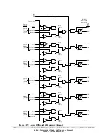
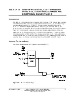
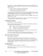
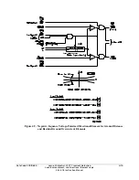
Inputs into the LOP logic are:
3PO three-pole open condition (indicates circuit breaker open condition
see Figure 5.5)
V
1
positive-sequence voltage (V secondary)
I
1
positive-sequence current (A secondary)
V
0
zero-sequence voltage (V secondary)
I
0
zero-sequence current (A secondary)
The circuit breaker has to be closed (Relay Word bit 3PO = logical 0) for the LOP logic to
operate.
Loss-of-potential is declared (Relay Word bit LOP = logical 1) when a 10 percent drop in V
1
is
detected, with no corresponding change in I
1
or I
0
. If the LOP condition persists for 60 cycles, it
latches in. LOP resets (Relay Word bit LOP = logical 0) when all three of the phase voltages
return above 30 V secondary and V
0
is less than 5 V secondary.
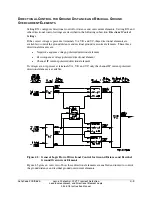
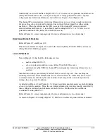
The loss-of-potential enable setting, ELOP, does not enable or disable the LOP logic. It just
routes the LOP Relay Word bit to different logic, as shown in Figure 4.1 and explained in the
remainder of this subsection.
Note that ILOP disables all distance elements (Figure 3.29 through Figure 3.37).
LOP is disabled while 3PO is asserted (breaker open). If all three potentials are lost during this
time, LOP will not assert when 3PO deasserts (breaker close) since the 10 percent drop in V
1
has
already occurred. This is the case for systems using either line-side or bus-side potential
transformers. LOP asserts on one or two missing potentials when 3PO deasserts, if phase
currents are balanced.
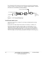
You may provide a SCADA alarm for bus-side potential transformers with the following
SEL
OGIC
expression:
SV1 = 3PO
OUT105 = !3P59 * SV1T + LOP
See Figure 3.50. Relay Word bit 3P59 asserts when A-phase, B-phase, and C-phase voltage
magnitudes are greater than setting 59P. Setting 59P should be at least 80 percent of nominal
voltage. Relay Word bit 3PO asserts when the circuit breaker is open. Set SV1PU longer than
the reclose open-time interval. In this expression, if any phase voltage is less than setting 59P
while the circuit breaker is open, or LOP is asserted, the expression is true (logical 1).
If the output is asserted, check the relay input potentials before closing the circuit breaker.
In a system using line-side potential transformers, remove SV1T from the expression. The alarm
will assert whenever the line is deenergized and will clear when the circuit breaker is closed if
system voltage is normal. If the output is asserted when the circuit breaker is closed, check the
relay input potentials.
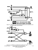
Setting ELOP = Y or Y1
If setting ELOP = Y or Y1 and a loss-of-potential condition occurs (Relay Word bit LOP asserts
to logical 1), negative-sequence voltage-polarized, zero-sequence voltage-polarized, and positive-
sequence voltage-polarized directional elements, plus all distance elements, are disabled by relay
word bit ILOP (see Figure 4.9, Figure 4.10, Figure 4.14, Figure 4.15, and Figure 3.29 through
Summary of Contents for SEL-311L
Page 6: ......
Page 8: ......
Page 26: ......
Page 54: ......
Page 144: ......
Page 216: ......
Page 252: ......
Page 302: ......
Page 338: ......
Page 480: ......
Page 484: ......
Page 486: ......
Page 502: ......
Page 532: ...12 28 Standard Event Reports and SER Date Code 20010625 SEL 311L Instruction Manual 4 ...
Page 552: ......
Page 554: ......
Page 574: ......
Page 576: ......
Page 596: ......
Page 602: ......
Page 628: ......
Page 656: ......
Page 662: ......
Page 664: ......
Page 688: ......
Page 700: ......
Page 716: ......
Page 722: ......
Page 734: ......