


Date Code 20010625
Line Current Differential Communications
10-1
and Serial Port Communications and Commands
SEL-311L Instruction Manual
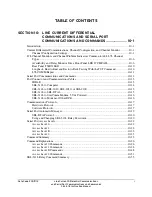
SECTION 10: LINE CURRENT DIFFERENTIAL
COMMUNICATIONS AND SERIAL PORT
COMMUNICATIONS AND COMMANDS
I
NTRODUCTION
This section describes SEL-311L Relay line current differential communications, and also
describes the serial communications used to set and interrogate the relay. The first part describes
87L communications, the 87L channel monitors, and settings related to 87L communications.
The second part describes EIA-232 and EIA-485 serial communications used to set, control and
interrogate the relay.
C
URRENT
D
IFFERENTIAL
C
OMMUNICATIONS
, C
HANNEL
C
ONFIGURATION
,
AND
C
HANNEL
M
ONITOR
Order the SEL-311L Relay with up to two line current differential interfaces. Each interface is
factory configured as EIA-422, CCITT G.703, IEEE PC37.94 compliant multimode fiber, or
1300 nm direct fiber. When the SEL-311L Relay arrives, the channels are configured per your
ordering options. Additional channel configuration settings optimize each channel interface to
your particular applications. The following sections describe each interface, and also describe
channel configuration settings particular to each interface type. After introducing each interface
type, this section describes the channel monitor indicators and monitor settings applicable to all
interface types.
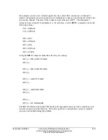
Use the
SET X
command to access the channel configuration settings and channel monitor
settings for line current differential channel interface X. Use the
SET Y
command for channel
interface Y. Alternatively, use the front panel
SET
command (see Figure 11.3).
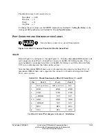
Channel Configuration Settings
EIA-422 Interface
The EIA-422 interface supplied in an SEL-311L Relay is isolated from the chassis to 1500 V
rms. Therefore the signal common is also isolated from the chassis, preventing ground loops.
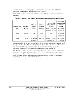
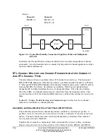
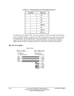
To preserve that isolation, ground the cable shield only at the multiplexer. Refer to Table 2.2 for
the EIA-422 cable appropriate to your application. All of the cables shown in Table 2.2 connect
the shield at the multiplexer end only. The DB-25 connector pinout on the SEL-311L Relay is
shown in Figure 2.6, and is per RS-530. Figure 2.6 also shows the direction of signal flow for an
EIA-422 interface.
Use the
SET Y
or
SET X
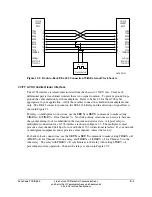
commands to select the clock polarity for transmit and receive clocks.
The receive clock polarity settings (RC422X and RC422Y) indicate the clock edge on which the
data should change. The transmit clock polarity clock settings (TC422X and TC422Y) indicate
clock sampling edges. For example, set TC422X = R if the multiplexer is set to sample transmit
data on the rising edge of the transmit clock (rising edge of signal TXCB on DB-25 pin 12,
falling edge of signal TXCA on DB-25 pin 15). Set RC422X = R if the multiplexer is set to
Summary of Contents for SEL-311L
Page 6: ......
Page 8: ......
Page 26: ......
Page 54: ......
Page 144: ......
Page 216: ......
Page 252: ......
Page 302: ......
Page 338: ......
Page 480: ......
Page 484: ......
Page 486: ......
Page 502: ......
Page 532: ...12 28 Standard Event Reports and SER Date Code 20010625 SEL 311L Instruction Manual 4 ...
Page 552: ......
Page 554: ......
Page 574: ......
Page 576: ......
Page 596: ......
Page 602: ......
Page 628: ......
Page 656: ......
Page 662: ......
Page 664: ......
Page 688: ......
Page 700: ......
Page 716: ......
Page 722: ......
Page 734: ......