
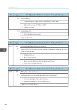
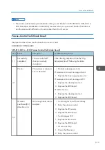


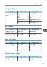

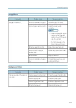


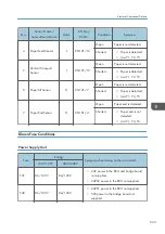


Missing Parts of Images
Symptom
Possible cause
Necessary actions
Some parts of images are
missing.
Defective PCDU
Replace the PCDU.
Defective image transfer belt
unit
Replace the image transfer belt
unit.
Defective paper transfer roller
Replace the paper transfer
roller.
Defective fusing unit
Replace the fusing unit.
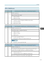
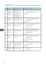
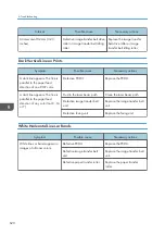
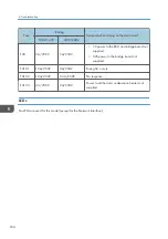
Dirty Background
Symptom
Possible cause
Necessary actions
Backgrounds of one CMYK
color are too dense.
Defective PCDU
Replace the PCDU.
Backgrounds of more than one
CMYK are too dense.color
Defective HVPS
Replace the HVPS.
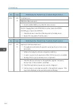
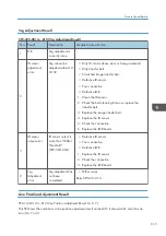
Partial CMY Color Dots
Symptom
Possible cause
Necessary actions
Unexpected dots of the same
color appear at irregular
intervals.
Defective PCDU
Replace the PCDU.
Defective image transfer belt
unit
Replace the image transfer belt
unit.
Defective fusing unit
Replace the fusing unit.
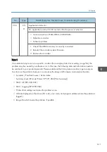
Dark Irregular Streaks on Prints
Symptom
Possible cause
Necessary actions
Unexpected streaks appear at
irregular intervals.
Defective image transfer belt
Replace the image transfer belt
unit.
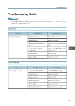
Troubleshooting Guide
621
Summary of Contents for Z-P2
Page 1: ...Model Z P2 Machine Codes M257 Field Service Manual April 2015 ...
Page 2: ......
Page 30: ...1 Product Information 28 ...
Page 73: ...9 Install the securing holder E 10 Reassemble the machine Tray Heater 71 ...
Page 86: ...3 Preventive Maintenance 84 ...
Page 92: ...5 Left cover B Right Cover 1 Open the duplex unit A 4 Replacement and Adjustment 90 ...
Page 128: ...5 Open the upper cover A 4 Replacement and Adjustment 126 ...
Page 131: ...4 The left stay A x 4 5 Rear holder bracket A x 2 Image Transfer 129 ...
Page 139: ...3 Remove the two screws 4 ID sensor board bracket A x 1 Image Transfer 137 ...
Page 141: ...4 Exit the SP mode Image Transfer 139 ...
Page 146: ...2 Temperature Humidity sensor A x 1 x 1 4 Replacement and Adjustment 144 ...
Page 187: ...3 Bracket A x 1 4 Release the paper feed unit A x 1 Paper Feed 185 ...
Page 201: ...5 Inner left upper cover page 94 6 Paper exit unit holder A x 1 Paper Exit 199 ...
Page 211: ...6 Release the left arm A x 1 Duplex Unit 209 ...
Page 215: ...3 Duplex lower guide plate A 4 Duplex upper guide plate A x 7 Duplex Unit 213 ...
Page 220: ...8 Right and left arms A x 2 each 4 Replacement and Adjustment 218 ...
Page 221: ...9 Duplex By pass motor bracket with the frame A x 6 10 Guide plate A x 4 Duplex Unit 219 ...
Page 245: ...5 Disconnect the connector 6 Disconnect the six connectors x 1 Electrical Components 243 ...
Page 254: ...4 Replacement and Adjustment 252 ...
Page 564: ...5 System Maintenance Reference 562 ...
Page 637: ...Model Z P2 Machine Codes M257 Appendices February 2015 ...
Page 638: ......
Page 640: ...2 ...
Page 648: ...1 Appendix Specifications 10 ...
Page 652: ...MEMO 14 ...
Page 653: ...MEMO 15 ...
Page 654: ...MEMO 16 EN ...