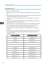


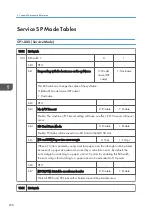


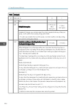


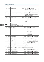

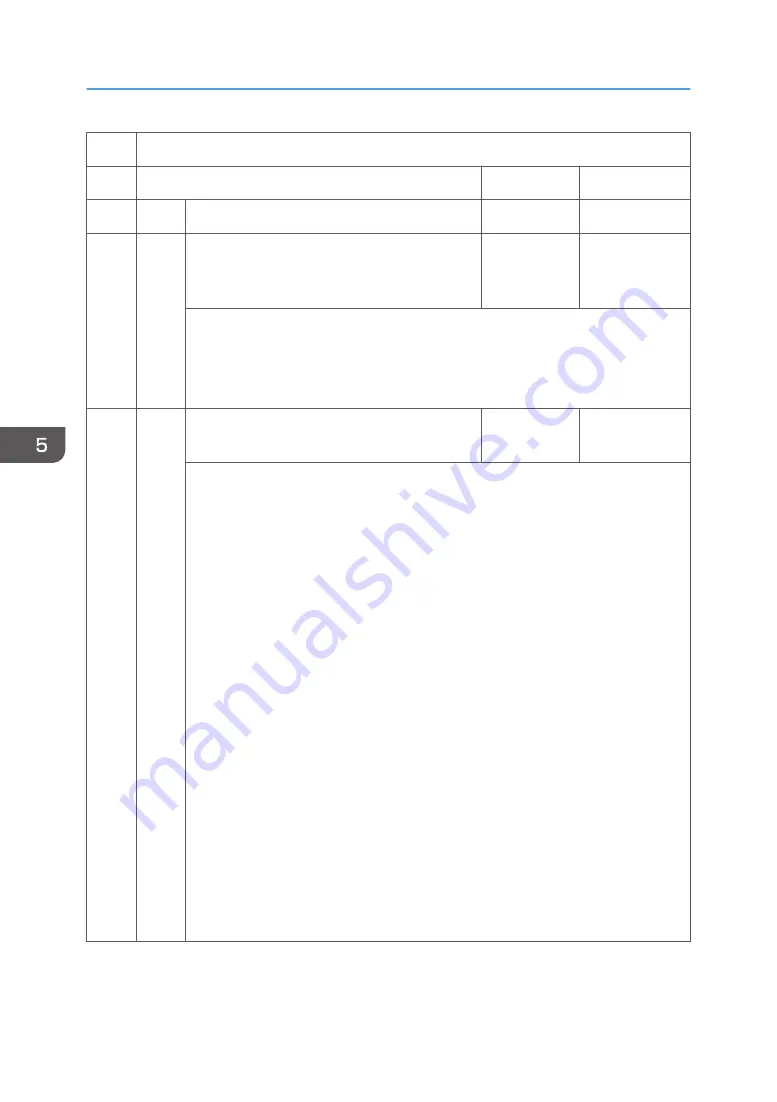
1001 Bit Switch
011 Bit Switch B
0
1
bit 0
DFU
-
-
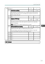
bit 1
Print job interruption
0: Does not
allow
interruption
1: Allow
interruption
0 (default): Print jobs are not interrupted. If a job is promoted to the top of the print
queue, it will wait for the currently printing job to finish.
1: If a job is promoted to the top of the queue, it will interrupt the currently printing
job and start printing immediately.
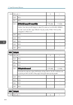
bit 2
Switch for enabling or disabling Limitless Paper
Feeding for the Bypass Tray
0: Enable
1: Disable
When the Bypass Tray is the target of the Auto Tray Select and Any Size/Type is
configured for the Tray Setting Priority setting of the Bypass Tray, this Bit Switch can
switch the behavior whether or not Limitless Paper Feeding is applied to the Bypass
Tray.* The default is Enabled (=0).
*Limitless Paper Feeding will try a matching tray of the next highest priority if a job
specified to Auto Tray Select as the tray setting is submitted and the tray runs out of
paper.
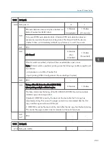
Enabled (=0: Default):
Limitless Paper Feeding is applied to the Bypass Tray.
If a tray other than the Bypass Tray matches the job's paper size and type but has run
out of paper, printing will occur from the Bypass Tray.
Disabled (=1):
Limitless Paper Feeding is not applied to the Bypass Tray.
If a tray other than the Bypass Tray matches the job's paper size and type but has run
out of paper, printing will stop and an alert will appear on the LCD screen, stating
that the tray has run out of paper. This prevents unexpected use of the Bypass Tray.
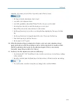
Limitations when this Bit Switch is set to "1":
- The "Paper Tray Priority: Printer" setting must be configured to a tray other than the
Bypass Tray.
- Jobs that contain more than one paper size cannot be printed.
5. System Maintenance Reference
264
Summary of Contents for Z-P2
Page 1: ...Model Z P2 Machine Codes M257 Field Service Manual April 2015 ...
Page 2: ......
Page 30: ...1 Product Information 28 ...
Page 73: ...9 Install the securing holder E 10 Reassemble the machine Tray Heater 71 ...
Page 86: ...3 Preventive Maintenance 84 ...
Page 92: ...5 Left cover B Right Cover 1 Open the duplex unit A 4 Replacement and Adjustment 90 ...
Page 128: ...5 Open the upper cover A 4 Replacement and Adjustment 126 ...
Page 131: ...4 The left stay A x 4 5 Rear holder bracket A x 2 Image Transfer 129 ...
Page 139: ...3 Remove the two screws 4 ID sensor board bracket A x 1 Image Transfer 137 ...
Page 141: ...4 Exit the SP mode Image Transfer 139 ...
Page 146: ...2 Temperature Humidity sensor A x 1 x 1 4 Replacement and Adjustment 144 ...
Page 187: ...3 Bracket A x 1 4 Release the paper feed unit A x 1 Paper Feed 185 ...
Page 201: ...5 Inner left upper cover page 94 6 Paper exit unit holder A x 1 Paper Exit 199 ...
Page 211: ...6 Release the left arm A x 1 Duplex Unit 209 ...
Page 215: ...3 Duplex lower guide plate A 4 Duplex upper guide plate A x 7 Duplex Unit 213 ...
Page 220: ...8 Right and left arms A x 2 each 4 Replacement and Adjustment 218 ...
Page 221: ...9 Duplex By pass motor bracket with the frame A x 6 10 Guide plate A x 4 Duplex Unit 219 ...
Page 245: ...5 Disconnect the connector 6 Disconnect the six connectors x 1 Electrical Components 243 ...
Page 254: ...4 Replacement and Adjustment 252 ...
Page 564: ...5 System Maintenance Reference 562 ...
Page 637: ...Model Z P2 Machine Codes M257 Appendices February 2015 ...
Page 638: ......
Page 640: ...2 ...
Page 648: ...1 Appendix Specifications 10 ...
Page 652: ...MEMO 14 ...
Page 653: ...MEMO 15 ...
Page 654: ...MEMO 16 EN ...