


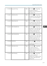


bit 4
Add "Apply Auto Paper Select" is the condition
that decides if the device's paper size or paper
type should be overwritten.
0: Disable
1: Enable
If this Bit Switch is set to "1" (enable), the "Apply Auto Paper Select" setting will
decide if the paper size or paper type that is specified in the device settings should
be overwritten by the job's commands when "Tray Setting Priority" is set to "Driver/
Command" or "Any Type".
- Apply Auto Paper Select = OFF: Overwritten (priority is given to the job’s
commands)
- Apply Auto Paper Select = ON: Not overwritten (priority is given to the device
settings)
bit 5
DFU
-
-
bit 6
DFU
-
-
bit 7
DFU
-
-
1001 Bit Switch
012 Bit Switch C DFU
-
-
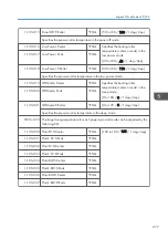
1003
[Clear Setting]
1003 001
Initialize System
Initializes settings in the System menu of the user
mode.
1003 003
Delete Program
DFU
1004
[Print Summary]
1004 001
Service Summary
Prints the service summary sheet (a summary of all
the controller settings).
1005
[Display Version]
1005 002
Printer Version
Displays the version of the controller firmware.
1007
[Supply Display]
Enables or disables the display for information on each consumable supply.
Service SP Mode Tables
265
Summary of Contents for Z-P2
Page 1: ...Model Z P2 Machine Codes M257 Field Service Manual April 2015 ...
Page 2: ......
Page 30: ...1 Product Information 28 ...
Page 73: ...9 Install the securing holder E 10 Reassemble the machine Tray Heater 71 ...
Page 86: ...3 Preventive Maintenance 84 ...
Page 92: ...5 Left cover B Right Cover 1 Open the duplex unit A 4 Replacement and Adjustment 90 ...
Page 128: ...5 Open the upper cover A 4 Replacement and Adjustment 126 ...
Page 131: ...4 The left stay A x 4 5 Rear holder bracket A x 2 Image Transfer 129 ...
Page 139: ...3 Remove the two screws 4 ID sensor board bracket A x 1 Image Transfer 137 ...
Page 141: ...4 Exit the SP mode Image Transfer 139 ...
Page 146: ...2 Temperature Humidity sensor A x 1 x 1 4 Replacement and Adjustment 144 ...
Page 187: ...3 Bracket A x 1 4 Release the paper feed unit A x 1 Paper Feed 185 ...
Page 201: ...5 Inner left upper cover page 94 6 Paper exit unit holder A x 1 Paper Exit 199 ...
Page 211: ...6 Release the left arm A x 1 Duplex Unit 209 ...
Page 215: ...3 Duplex lower guide plate A 4 Duplex upper guide plate A x 7 Duplex Unit 213 ...
Page 220: ...8 Right and left arms A x 2 each 4 Replacement and Adjustment 218 ...
Page 221: ...9 Duplex By pass motor bracket with the frame A x 6 10 Guide plate A x 4 Duplex Unit 219 ...
Page 245: ...5 Disconnect the connector 6 Disconnect the six connectors x 1 Electrical Components 243 ...
Page 254: ...4 Replacement and Adjustment 252 ...
Page 564: ...5 System Maintenance Reference 562 ...
Page 637: ...Model Z P2 Machine Codes M257 Appendices February 2015 ...
Page 638: ......
Page 640: ...2 ...
Page 648: ...1 Appendix Specifications 10 ...
Page 652: ...MEMO 14 ...
Page 653: ...MEMO 15 ...
Page 654: ...MEMO 16 EN ...