
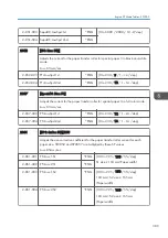


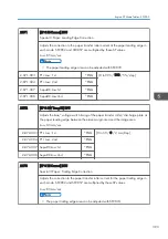


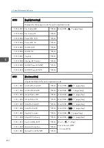
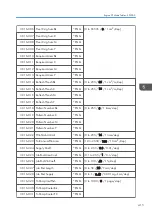

3-041-004 Pre-ACC Proc Ctrl
*ENG [0 to 2 / 2 / 1/step]
0: Not Execute
1: Process Control
2: TC Control
Selects the process control mode that is done before ACC.
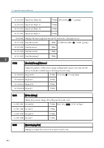
3-041-005 Pat Calc Method
*ENG
[0 to 2 / 0 / 1/step]
0: FIXED
1: INITIALIZED
2: CALCULATED
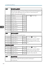
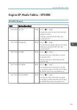
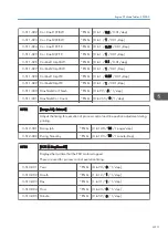
3043
[TD Adjust Mode]
3-043-001 Rept Nmbr:PowerON
*ENG [0 to 9 / 4 / 1 time/step]
Specifies the maximum number of repeats of the toner density adjustment at power on.
0: Disabled, 1 to 3: Repeat number,
4: Repeat three times (No consumption mode)
5: Repeat three times (Toner is supplied only when the toner density is too low, and
toner is consumed only when the toner density is too dark.)
6 to 9: Disabled
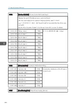
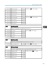
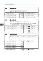
3-043-002 Rept Nmbr:Initial
*ENG [0 to 9 / 3 / 1 time/step]
Specifies the maximum number of repeats of the toner density adjustment at the
developer initialization.
0: Disabled, 1 to 3: Repeat number,
4: Repeat three times (No consumption mode)
5: Repeat three times (Toner is supplied only when the toner density is too low, and
toner is consumed only when the toner density is too dark.)
6 to 9: Disabled
5. System Maintenance Reference
400
Summary of Contents for Z-P2
Page 1: ...Model Z P2 Machine Codes M257 Field Service Manual April 2015 ...
Page 2: ......
Page 30: ...1 Product Information 28 ...
Page 73: ...9 Install the securing holder E 10 Reassemble the machine Tray Heater 71 ...
Page 86: ...3 Preventive Maintenance 84 ...
Page 92: ...5 Left cover B Right Cover 1 Open the duplex unit A 4 Replacement and Adjustment 90 ...
Page 128: ...5 Open the upper cover A 4 Replacement and Adjustment 126 ...
Page 131: ...4 The left stay A x 4 5 Rear holder bracket A x 2 Image Transfer 129 ...
Page 139: ...3 Remove the two screws 4 ID sensor board bracket A x 1 Image Transfer 137 ...
Page 141: ...4 Exit the SP mode Image Transfer 139 ...
Page 146: ...2 Temperature Humidity sensor A x 1 x 1 4 Replacement and Adjustment 144 ...
Page 187: ...3 Bracket A x 1 4 Release the paper feed unit A x 1 Paper Feed 185 ...
Page 201: ...5 Inner left upper cover page 94 6 Paper exit unit holder A x 1 Paper Exit 199 ...
Page 211: ...6 Release the left arm A x 1 Duplex Unit 209 ...
Page 215: ...3 Duplex lower guide plate A 4 Duplex upper guide plate A x 7 Duplex Unit 213 ...
Page 220: ...8 Right and left arms A x 2 each 4 Replacement and Adjustment 218 ...
Page 221: ...9 Duplex By pass motor bracket with the frame A x 6 10 Guide plate A x 4 Duplex Unit 219 ...
Page 245: ...5 Disconnect the connector 6 Disconnect the six connectors x 1 Electrical Components 243 ...
Page 254: ...4 Replacement and Adjustment 252 ...
Page 564: ...5 System Maintenance Reference 562 ...
Page 637: ...Model Z P2 Machine Codes M257 Appendices February 2015 ...
Page 638: ......
Page 640: ...2 ...
Page 648: ...1 Appendix Specifications 10 ...
Page 652: ...MEMO 14 ...
Page 653: ...MEMO 15 ...
Page 654: ...MEMO 16 EN ...