


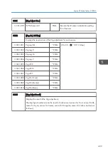


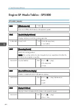


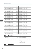


3514
[Env Disp:Job End]
Displays the environmental conditions at the last job.
These are used for process control execution timing.
3-514-001 Temperature
*ENG [-1280 to 1270 / 0 / 0.1°C/step]
3-514-002 Relative Humidity
*ENG [0 to 1000 / - / 0.1%RH/step]
3-514-003 Absolute Humidity
*ENG [0 to 1000 / - / 0.1 g/cm
3
/step]
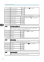
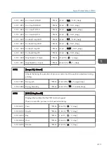
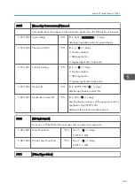
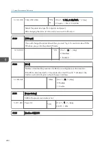
3515
[Exec Intvl:Disp]
Displays the current interval for process control execution.
When the machine calculates the timing for process control, it uses a number of
conditions. These are the results after considering all the conditions.
3-515-001 Job End:ProCon:BW
*ENG [0 to 2000 / 500 / 1 page/step]
3-515-002 Job End:ProCon:FC
*ENG [0 to 2000 / 200 / 1 page/step]
3-515-003 Intrrpt:ProCon:BW
*ENG [0 to 2000 / 500 / 1 page/step]
3-515-004 Intrrpt:ProCon:FC
*ENG [0 to 2000 / 200 / 1 page/step]
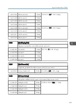
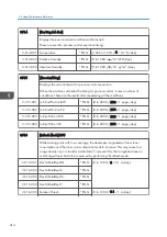
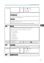
3516
[Refresh Mode] DFU
While making prints with low coverage, the developer is agitated with less toner
consumption and the toner carrier attraction tends to increase. This may cause low
image density or poor transfer (white dots). To prevent this, the coagulated toner or
overcharged toner has to be consumed by performing the refresh mode.
3-516-001 Dev.MRotatDspl:Bk
*ENG [0 to 1000 / 0 / 0.1 m/step]
3-516-002 Dev.MRotatDspl:C
*ENG
3-516-003 Dev.MRotatDspl:M
*ENG
3-516-004 Dev.MRotatDspl:Y
*ENG
3-516-005 Rotation Thresh
*ENG [0 to 1000 / 0.1 / 1 m/step]
5. System Maintenance Reference
414
Summary of Contents for Z-P2
Page 1: ...Model Z P2 Machine Codes M257 Field Service Manual April 2015 ...
Page 2: ......
Page 30: ...1 Product Information 28 ...
Page 73: ...9 Install the securing holder E 10 Reassemble the machine Tray Heater 71 ...
Page 86: ...3 Preventive Maintenance 84 ...
Page 92: ...5 Left cover B Right Cover 1 Open the duplex unit A 4 Replacement and Adjustment 90 ...
Page 128: ...5 Open the upper cover A 4 Replacement and Adjustment 126 ...
Page 131: ...4 The left stay A x 4 5 Rear holder bracket A x 2 Image Transfer 129 ...
Page 139: ...3 Remove the two screws 4 ID sensor board bracket A x 1 Image Transfer 137 ...
Page 141: ...4 Exit the SP mode Image Transfer 139 ...
Page 146: ...2 Temperature Humidity sensor A x 1 x 1 4 Replacement and Adjustment 144 ...
Page 187: ...3 Bracket A x 1 4 Release the paper feed unit A x 1 Paper Feed 185 ...
Page 201: ...5 Inner left upper cover page 94 6 Paper exit unit holder A x 1 Paper Exit 199 ...
Page 211: ...6 Release the left arm A x 1 Duplex Unit 209 ...
Page 215: ...3 Duplex lower guide plate A 4 Duplex upper guide plate A x 7 Duplex Unit 213 ...
Page 220: ...8 Right and left arms A x 2 each 4 Replacement and Adjustment 218 ...
Page 221: ...9 Duplex By pass motor bracket with the frame A x 6 10 Guide plate A x 4 Duplex Unit 219 ...
Page 245: ...5 Disconnect the connector 6 Disconnect the six connectors x 1 Electrical Components 243 ...
Page 254: ...4 Replacement and Adjustment 252 ...
Page 564: ...5 System Maintenance Reference 562 ...
Page 637: ...Model Z P2 Machine Codes M257 Appendices February 2015 ...
Page 638: ......
Page 640: ...2 ...
Page 648: ...1 Appendix Specifications 10 ...
Page 652: ...MEMO 14 ...
Page 653: ...MEMO 15 ...
Page 654: ...MEMO 16 EN ...