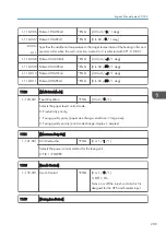


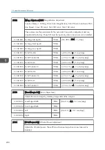


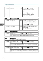


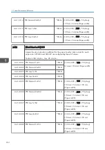


2-193-010 Magnification
*ENG
[0 to 10 / 1 / 0.1 %/step]
Adjusts the magnification threshold for line position adjustment. If the length of the
main scan is changed by this amount since the previous MUSIC, then MUSIC is done
again.
2-193-011 Temp. 2
*ENG
[0 to 100 / 10 / 1 deg/step]
Adjusts the temperature change threshold for the line position adjustment (Mode a:
adjustment twice). The timing for line position adjustment depends on the combinations
of several conditions.
2-193-012 Time 2
*ENG
[1 to 9999 / 600 / 1 minute/step]
Adjusts the time threshold for the line position adjustment (Mode a: adjustment twice).
The timing for line position adjustment depends on the combinations of several
conditions.
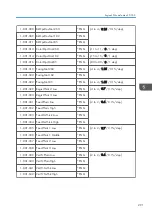
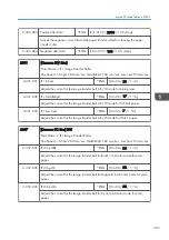
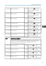
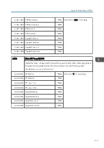
2-193-013 Time 3
*ENG
[1 to 1440 / 300 / 1 minute/step]
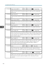
2-193-014 Pg:FCJbBef:BW+FC
*ENG
[0 to 999 / 200 / 1 page/step]
2-193-015 Pg:FCJobBef:FC
*ENG
[0 to 999 / 200 / 1 page/step]
2-193-016 Pg:PowerON:BW+FC
*ENG
[0 to 999 / 200 / 1 page/step]
Adjusts the threshold of the line position adjustment for BW and FC printing mode at
the power-on. The line position adjustment is done when the number of outputs in
monochrome and color printing mode reaches the value specified with this SP and the
other conditions such as the temperature change and time elapsing are satisfied.
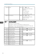
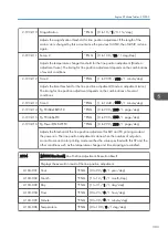
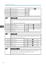
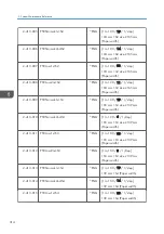
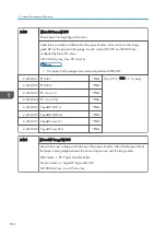
2194
[MUSIC Exe Result] Line Position Adjustment: Execution Result
Displays the execution result of the line position adjustment.
2-194-001 Year
*ENG
[0 to 99 / 0 / 1 year/step]
2-194-002 Month
*ENG
[1 to 12 / 1 / 1 month/step]
2-194-003 Day
*ENG
[1 to 31 / 1 / 1 day/step]
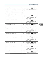
2-194-004 Hour
*ENG
[0 to 23 / 0 / 1 hour/step]
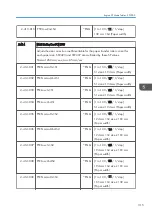
2-194-005 Minute
*ENG
[0 to 59 / 0 / 1 minute/step]
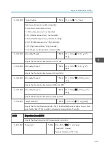
2-194-006 Temperature
*ENG
[0 to 100 / 0 / 1 deg/step]
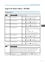
Engine SP Mode Tables - SP2000
303
Summary of Contents for Z-P2
Page 1: ...Model Z P2 Machine Codes M257 Field Service Manual April 2015 ...
Page 2: ......
Page 30: ...1 Product Information 28 ...
Page 73: ...9 Install the securing holder E 10 Reassemble the machine Tray Heater 71 ...
Page 86: ...3 Preventive Maintenance 84 ...
Page 92: ...5 Left cover B Right Cover 1 Open the duplex unit A 4 Replacement and Adjustment 90 ...
Page 128: ...5 Open the upper cover A 4 Replacement and Adjustment 126 ...
Page 131: ...4 The left stay A x 4 5 Rear holder bracket A x 2 Image Transfer 129 ...
Page 139: ...3 Remove the two screws 4 ID sensor board bracket A x 1 Image Transfer 137 ...
Page 141: ...4 Exit the SP mode Image Transfer 139 ...
Page 146: ...2 Temperature Humidity sensor A x 1 x 1 4 Replacement and Adjustment 144 ...
Page 187: ...3 Bracket A x 1 4 Release the paper feed unit A x 1 Paper Feed 185 ...
Page 201: ...5 Inner left upper cover page 94 6 Paper exit unit holder A x 1 Paper Exit 199 ...
Page 211: ...6 Release the left arm A x 1 Duplex Unit 209 ...
Page 215: ...3 Duplex lower guide plate A 4 Duplex upper guide plate A x 7 Duplex Unit 213 ...
Page 220: ...8 Right and left arms A x 2 each 4 Replacement and Adjustment 218 ...
Page 221: ...9 Duplex By pass motor bracket with the frame A x 6 10 Guide plate A x 4 Duplex Unit 219 ...
Page 245: ...5 Disconnect the connector 6 Disconnect the six connectors x 1 Electrical Components 243 ...
Page 254: ...4 Replacement and Adjustment 252 ...
Page 564: ...5 System Maintenance Reference 562 ...
Page 637: ...Model Z P2 Machine Codes M257 Appendices February 2015 ...
Page 638: ......
Page 640: ...2 ...
Page 648: ...1 Appendix Specifications 10 ...
Page 652: ...MEMO 14 ...
Page 653: ...MEMO 15 ...
Page 654: ...MEMO 16 EN ...