


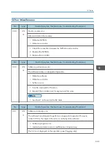
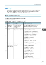
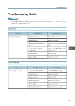


No.
Type
Details (Symptom, Possible Cause, Troubleshooting Procedures)
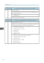
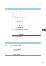
998
CTL
D
Application start error
No applications start within 60 seconds after the power is turned on.
• Loose connection of RAM-DIMM, ROM-DIMM
• Defective controller
• Software problem
1. Check if the DIMM memory is correctly connected.
2. Reinstall the controller system firmware.
3. Replace the controller.
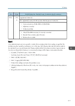
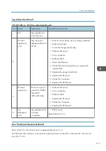
Note 1
If a problem always occurs in a specific condition (for example. printer driver setting, image file), the
problem may be caused by a software error. In this case, the following data and information needs to
be sent back to your product specialist. Please understand that it may take some time to get a reply on
how to solve the problem, because in some cases the design staff in Japan must analyze the data.
• Symptom / Possible Causes / Action taken
• Summary sheet (SP mode "Printer SP", SP1-004 [Print Summary])
• SMC - All (SP5-990-001)
• SMC - Logging (SP5-990-004)
• Printer driver settings used when the problem occurs
• All data displayed on the screen (SC code, error code, and program address where the problem is
logged.)
• Image file which causes the problem, if possible
SC Tables
611
Summary of Contents for Z-P2
Page 1: ...Model Z P2 Machine Codes M257 Field Service Manual April 2015 ...
Page 2: ......
Page 30: ...1 Product Information 28 ...
Page 73: ...9 Install the securing holder E 10 Reassemble the machine Tray Heater 71 ...
Page 86: ...3 Preventive Maintenance 84 ...
Page 92: ...5 Left cover B Right Cover 1 Open the duplex unit A 4 Replacement and Adjustment 90 ...
Page 128: ...5 Open the upper cover A 4 Replacement and Adjustment 126 ...
Page 131: ...4 The left stay A x 4 5 Rear holder bracket A x 2 Image Transfer 129 ...
Page 139: ...3 Remove the two screws 4 ID sensor board bracket A x 1 Image Transfer 137 ...
Page 141: ...4 Exit the SP mode Image Transfer 139 ...
Page 146: ...2 Temperature Humidity sensor A x 1 x 1 4 Replacement and Adjustment 144 ...
Page 187: ...3 Bracket A x 1 4 Release the paper feed unit A x 1 Paper Feed 185 ...
Page 201: ...5 Inner left upper cover page 94 6 Paper exit unit holder A x 1 Paper Exit 199 ...
Page 211: ...6 Release the left arm A x 1 Duplex Unit 209 ...
Page 215: ...3 Duplex lower guide plate A 4 Duplex upper guide plate A x 7 Duplex Unit 213 ...
Page 220: ...8 Right and left arms A x 2 each 4 Replacement and Adjustment 218 ...
Page 221: ...9 Duplex By pass motor bracket with the frame A x 6 10 Guide plate A x 4 Duplex Unit 219 ...
Page 245: ...5 Disconnect the connector 6 Disconnect the six connectors x 1 Electrical Components 243 ...
Page 254: ...4 Replacement and Adjustment 252 ...
Page 564: ...5 System Maintenance Reference 562 ...
Page 637: ...Model Z P2 Machine Codes M257 Appendices February 2015 ...
Page 638: ......
Page 640: ...2 ...
Page 648: ...1 Appendix Specifications 10 ...
Page 652: ...MEMO 14 ...
Page 653: ...MEMO 15 ...
Page 654: ...MEMO 16 EN ...