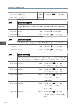

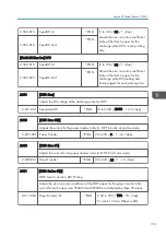


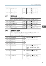
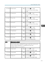


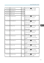


2-657-001 PTr : 1st
*ENG
[0 to 50 / 0 / 2 mm/step]
2-657-002 PTr : 2nd
*ENG
2-657-003 SepaDC:1st
*ENG
2-657-004 SepaDC:2nd
*ENG
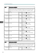
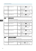
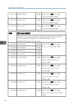
2660
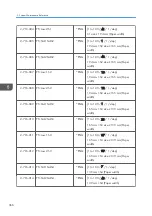
[Thick3: EnvCor] DFU
Thick 3 Paper: MM Environment Coefficient Adjustment
2-660-015 SepaDC:1st
*ENG
[1 to 100 / 30 / 1 /step]
Adjusts the size correction coefficient
table of the thick 3 paper for the
discharge plate DC for each printing
side.
2-660-016
SepaDC:2nd
*ENG
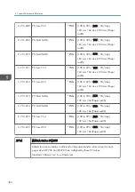
[TThick3:Ed-Env.Cor] DFU
2-660-019 SepaDC:1st
*ENG
[1 to 100 / 30 / 1 /step]
Adjusts the size correction coefficient
table of the thick 3 paper for the
discharge plate DC (leading and traiing
edges) for each printing side.
2-660-020
SepaDC:2nd
*ENG
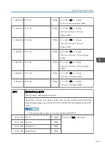
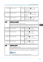
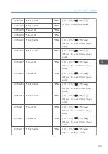
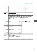
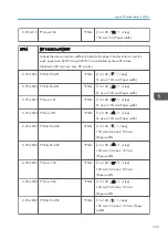
2701
[MThick: Bias]
Adjusts the DC voltage of the discharge plate for middle thick paper.
2-701-001 SepaDC:StdSpd:1st
*ENG
[0 to 6000 / 2000 / 10 -V /step]
2-701-002 SepaDC:StdSpd:2nd
*ENG
2-701-003 SepaDC:LowSpd:1st
*ENG
2-701-004 SepaDC:LowSpd:2nd
*ENG
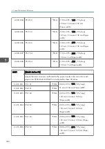
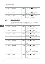
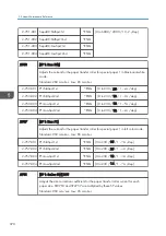
2703
[MThick:Bias:BW]
Standard: 260mm/sec, Low: 85mm/sec
Adjusts the current for the paper transfer roller for middle thick in black-and-white
mode.
2-703-001 PTr:StdSpd:1st
*ENG
[0 to 230 / 20 / 1- A /step]
5. System Maintenance Reference
360
Summary of Contents for Z-P2
Page 1: ...Model Z P2 Machine Codes M257 Field Service Manual April 2015 ...
Page 2: ......
Page 30: ...1 Product Information 28 ...
Page 73: ...9 Install the securing holder E 10 Reassemble the machine Tray Heater 71 ...
Page 86: ...3 Preventive Maintenance 84 ...
Page 92: ...5 Left cover B Right Cover 1 Open the duplex unit A 4 Replacement and Adjustment 90 ...
Page 128: ...5 Open the upper cover A 4 Replacement and Adjustment 126 ...
Page 131: ...4 The left stay A x 4 5 Rear holder bracket A x 2 Image Transfer 129 ...
Page 139: ...3 Remove the two screws 4 ID sensor board bracket A x 1 Image Transfer 137 ...
Page 141: ...4 Exit the SP mode Image Transfer 139 ...
Page 146: ...2 Temperature Humidity sensor A x 1 x 1 4 Replacement and Adjustment 144 ...
Page 187: ...3 Bracket A x 1 4 Release the paper feed unit A x 1 Paper Feed 185 ...
Page 201: ...5 Inner left upper cover page 94 6 Paper exit unit holder A x 1 Paper Exit 199 ...
Page 211: ...6 Release the left arm A x 1 Duplex Unit 209 ...
Page 215: ...3 Duplex lower guide plate A 4 Duplex upper guide plate A x 7 Duplex Unit 213 ...
Page 220: ...8 Right and left arms A x 2 each 4 Replacement and Adjustment 218 ...
Page 221: ...9 Duplex By pass motor bracket with the frame A x 6 10 Guide plate A x 4 Duplex Unit 219 ...
Page 245: ...5 Disconnect the connector 6 Disconnect the six connectors x 1 Electrical Components 243 ...
Page 254: ...4 Replacement and Adjustment 252 ...
Page 564: ...5 System Maintenance Reference 562 ...
Page 637: ...Model Z P2 Machine Codes M257 Appendices February 2015 ...
Page 638: ......
Page 640: ...2 ...
Page 648: ...1 Appendix Specifications 10 ...
Page 652: ...MEMO 14 ...
Page 653: ...MEMO 15 ...
Page 654: ...MEMO 16 EN ...