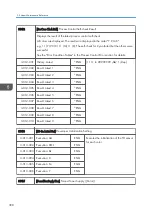


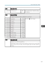

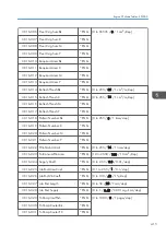


3510
[ImgAdj.Cuntr:Dspl]
Displays the total page counter for each adjustment mode.
3-510-001 Pro.Control:BW
*ENG [0 to 2000 / 0 / 1 page/step]
3-510-002 Pro.Control:FC
*ENG
3-510-003 Power ON: BW
*ENG
3-510-004 Power ON: FC
*ENG
3-510-005 MUSIC: BW
*ENG
3-510-006 MUSIC: FC
*ENG
3-510-007 Vsg Adj.
*ENG
3-510-008 Charge AC Control
*ENG
3-510-009 MUSIC:Power ON:BW
*ENG
3-510-010 MUSIC:Power ON:FC
*ENG
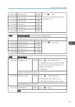
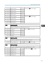
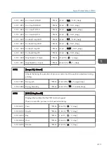
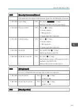
3511
[Exe.Interval:Set]
Adjusts the threshold for each adjustment mode.
3-511-001 Job End:ProCon:BW
*ENG [0 to 2000 / 250 / 1 page/step]
3-511-002 Job End:ProCon:FC
*ENG [0 to 2000 / 85 / 1 page/step]
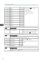
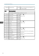
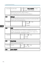
3-511-003 Intrrpt:ProCon:BW
*ENG [0 to 2000 / 500 / 1 page/step]
3-511-004 Intrrpt:ProCon:FC
*ENG [0 to 2000 / 200 / 1 page/step]
3-511-005 Initial:ProCon:BW
*ENG [0 to 2000 / 250 / 1 page/step]
3-511-006 Initial:ProCon:FC
*ENG [0 to 2000 / 100 / 1 page/step]
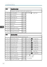
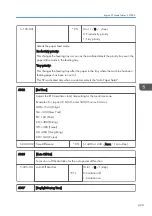
3-511-007 Vsg Adj. Counter
*ENG [0 to 2000 / 0 / 1 page/step]
3-511-008 ChrgAC Ctrl Count
*ENG [0 to 2000 / 500 / 1 page/step]
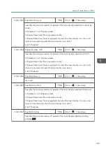
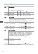
3-511-019 Env.Crrct:ON/OFF
*ENG [0 or 1 / 1 / 1 /step]
0: Not Correct (OFF),
1: Correct (ON)
3-511-020 Gamma Correction
*ENG
3-511-021 NoUseT Cor:ON/OFF
*ENG
5. System Maintenance Reference
412
Summary of Contents for Z-P2
Page 1: ...Model Z P2 Machine Codes M257 Field Service Manual April 2015 ...
Page 2: ......
Page 30: ...1 Product Information 28 ...
Page 73: ...9 Install the securing holder E 10 Reassemble the machine Tray Heater 71 ...
Page 86: ...3 Preventive Maintenance 84 ...
Page 92: ...5 Left cover B Right Cover 1 Open the duplex unit A 4 Replacement and Adjustment 90 ...
Page 128: ...5 Open the upper cover A 4 Replacement and Adjustment 126 ...
Page 131: ...4 The left stay A x 4 5 Rear holder bracket A x 2 Image Transfer 129 ...
Page 139: ...3 Remove the two screws 4 ID sensor board bracket A x 1 Image Transfer 137 ...
Page 141: ...4 Exit the SP mode Image Transfer 139 ...
Page 146: ...2 Temperature Humidity sensor A x 1 x 1 4 Replacement and Adjustment 144 ...
Page 187: ...3 Bracket A x 1 4 Release the paper feed unit A x 1 Paper Feed 185 ...
Page 201: ...5 Inner left upper cover page 94 6 Paper exit unit holder A x 1 Paper Exit 199 ...
Page 211: ...6 Release the left arm A x 1 Duplex Unit 209 ...
Page 215: ...3 Duplex lower guide plate A 4 Duplex upper guide plate A x 7 Duplex Unit 213 ...
Page 220: ...8 Right and left arms A x 2 each 4 Replacement and Adjustment 218 ...
Page 221: ...9 Duplex By pass motor bracket with the frame A x 6 10 Guide plate A x 4 Duplex Unit 219 ...
Page 245: ...5 Disconnect the connector 6 Disconnect the six connectors x 1 Electrical Components 243 ...
Page 254: ...4 Replacement and Adjustment 252 ...
Page 564: ...5 System Maintenance Reference 562 ...
Page 637: ...Model Z P2 Machine Codes M257 Appendices February 2015 ...
Page 638: ......
Page 640: ...2 ...
Page 648: ...1 Appendix Specifications 10 ...
Page 652: ...MEMO 14 ...
Page 653: ...MEMO 15 ...
Page 654: ...MEMO 16 EN ...