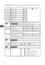


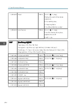


2102
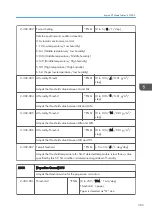
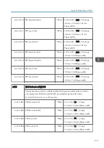
[Mag. Adjustment] DFU Magnification Adjustment
Function Name -> M Mag.: Main Scan Magnification, M B-P: Main Scan Beam Pitch
Line Speed -> Low: 85 mm/s, Std: 260 mm/s, Mid: 182 mm/s
These values are the parameters for the automatic line position adjustment and are
adjusted at the factory. These SPs must be input only when a new laser unit is installed.
2-102-001 M Mag.: Std Spd K
*ENG
[0 to 408 / 204 / 1 /step]
2-102-002 M Mag.: Mid Spd K
*ENG
2-102-003 M Mag.: Low Spd K
*ENG
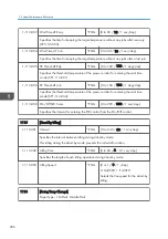
2-102-013 M B-P Dot: Bk
*ENG
[–20 to 20 / 9 / 1 dot/step]
2-102-014 M B-P Subdot: Bk
*ENG
[–15 to 15 / -3 / 1 sub-dot/step]
2-102-015 M B-P Dot: C
*ENG
[–20 to 20 / 9 / 1 dot/step]
2-102-016 M B-P Subdot: C
*ENG
[–15 to 15 / -3 / 1 sub-dot/step]
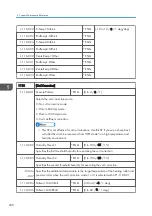
2-102-017 M B-P Dot: M
*ENG
[–20 to 20 / 9 / 1 dot/step]
2-102-018 M B-P Subdot: M
*ENG
[–15 to 15 / -4 / 1 sub-dot/step]
2-102-019 M B-P Dot: Y
*ENG
[–20 to 20 / 9 / 1 dot/step]
2-102-020 M B-P Subdot: Y
*ENG
[–15 to 15 / -4 / 1 sub-dot/step]
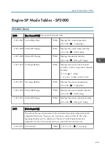
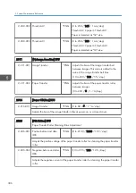
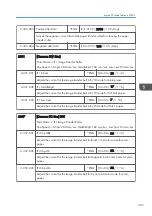
2103
[EraseMargin Adj.] (Area, Paper Size)
Adjusts the erase margin by deleting image data at the margins.
2-103-001 Lead Edge Width
*ENG
[0 to 9.9 / 4.2 / 0.1 mm/step]
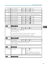
2-103-002 Trail. Edge Width
*ENG
2-103-003 Left
*ENG
[0 to 9.9 / 2 / 0.1 mm/step]
2-103-004 Right
*ENG
2104
[LD IntlPower Adj.] LD Initial Power Adjustment
Adjusts the LD initial power. These SPs must be input only when a new laser unit is
installed.
5. System Maintenance Reference
298
Summary of Contents for Z-P2
Page 1: ...Model Z P2 Machine Codes M257 Field Service Manual April 2015 ...
Page 2: ......
Page 30: ...1 Product Information 28 ...
Page 73: ...9 Install the securing holder E 10 Reassemble the machine Tray Heater 71 ...
Page 86: ...3 Preventive Maintenance 84 ...
Page 92: ...5 Left cover B Right Cover 1 Open the duplex unit A 4 Replacement and Adjustment 90 ...
Page 128: ...5 Open the upper cover A 4 Replacement and Adjustment 126 ...
Page 131: ...4 The left stay A x 4 5 Rear holder bracket A x 2 Image Transfer 129 ...
Page 139: ...3 Remove the two screws 4 ID sensor board bracket A x 1 Image Transfer 137 ...
Page 141: ...4 Exit the SP mode Image Transfer 139 ...
Page 146: ...2 Temperature Humidity sensor A x 1 x 1 4 Replacement and Adjustment 144 ...
Page 187: ...3 Bracket A x 1 4 Release the paper feed unit A x 1 Paper Feed 185 ...
Page 201: ...5 Inner left upper cover page 94 6 Paper exit unit holder A x 1 Paper Exit 199 ...
Page 211: ...6 Release the left arm A x 1 Duplex Unit 209 ...
Page 215: ...3 Duplex lower guide plate A 4 Duplex upper guide plate A x 7 Duplex Unit 213 ...
Page 220: ...8 Right and left arms A x 2 each 4 Replacement and Adjustment 218 ...
Page 221: ...9 Duplex By pass motor bracket with the frame A x 6 10 Guide plate A x 4 Duplex Unit 219 ...
Page 245: ...5 Disconnect the connector 6 Disconnect the six connectors x 1 Electrical Components 243 ...
Page 254: ...4 Replacement and Adjustment 252 ...
Page 564: ...5 System Maintenance Reference 562 ...
Page 637: ...Model Z P2 Machine Codes M257 Appendices February 2015 ...
Page 638: ......
Page 640: ...2 ...
Page 648: ...1 Appendix Specifications 10 ...
Page 652: ...MEMO 14 ...
Page 653: ...MEMO 15 ...
Page 654: ...MEMO 16 EN ...