


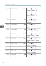

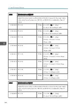
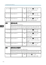


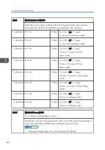
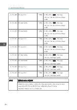

2-564-004 PTr:2:S1
*ENG [1 to 100 / 38 / 1 /step]
S1 size ≥ 194 mm (Paper width)
2-564-007 PTr:1:S2
*ENG [1 to 100 / 13 / 1 /step]
194 mm > S2 size ≥ 165 mm
(Paper width)
2-564-008 PTr:2:S2
*ENG [1 to 100 / 38 / 1 /step]
194 mm > S2 size ≥ 165 mm
(Paper width)
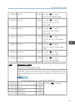
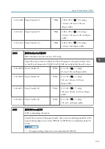
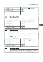
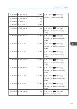
2-564-011 PTr:1:S3
*ENG [1 to 100 / 13 / 1 /step]
165 mm > S3 size ≥ 139 mm (Paper
width)
2-564-012 PTr:2:S3
*ENG [1 to 100 / 38 / 1 /step]
165 mm > S3 size ≥ 139 mm (Paper
width)
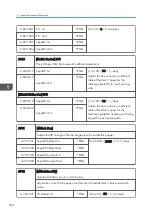
2-564-015 PTr:1:S4
*ENG [1 to 100 / 13 / 1 /step]
139 mm > S4 (Paper width)
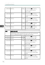
2-564-016 PTr:2:S4
*ENG [1 to 100 / 38 / 1 /step]
139 mm > S4 (Paper width)
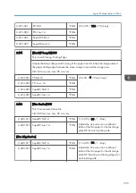
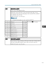
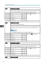
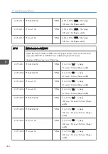
2571
[Thick2:LE Correct] DFU
Thick 2 Paper: Leading Edge Correction
Adjusts the correction to the paper transfer roller current or discharge plate DC at the
paper leading edge in each mode. SP2553 and SP2558 are multiplied by these SP
values.
• The paper leading edge area can be adjusted with SP2572.
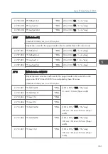
2-571-001 PTr: 1st
*ENG
[0 to 995 / 100 / 5%/step]
2-571-002 PTr: 2nd
*ENG
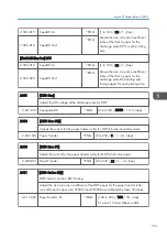
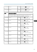
2-571-003 SepaDC:1st
*ENG
2-571-004 SepaDC:2nd
*ENG
Engine SP Mode Tables - SP2000
349
Summary of Contents for Z-P2
Page 1: ...Model Z P2 Machine Codes M257 Field Service Manual April 2015 ...
Page 2: ......
Page 30: ...1 Product Information 28 ...
Page 73: ...9 Install the securing holder E 10 Reassemble the machine Tray Heater 71 ...
Page 86: ...3 Preventive Maintenance 84 ...
Page 92: ...5 Left cover B Right Cover 1 Open the duplex unit A 4 Replacement and Adjustment 90 ...
Page 128: ...5 Open the upper cover A 4 Replacement and Adjustment 126 ...
Page 131: ...4 The left stay A x 4 5 Rear holder bracket A x 2 Image Transfer 129 ...
Page 139: ...3 Remove the two screws 4 ID sensor board bracket A x 1 Image Transfer 137 ...
Page 141: ...4 Exit the SP mode Image Transfer 139 ...
Page 146: ...2 Temperature Humidity sensor A x 1 x 1 4 Replacement and Adjustment 144 ...
Page 187: ...3 Bracket A x 1 4 Release the paper feed unit A x 1 Paper Feed 185 ...
Page 201: ...5 Inner left upper cover page 94 6 Paper exit unit holder A x 1 Paper Exit 199 ...
Page 211: ...6 Release the left arm A x 1 Duplex Unit 209 ...
Page 215: ...3 Duplex lower guide plate A 4 Duplex upper guide plate A x 7 Duplex Unit 213 ...
Page 220: ...8 Right and left arms A x 2 each 4 Replacement and Adjustment 218 ...
Page 221: ...9 Duplex By pass motor bracket with the frame A x 6 10 Guide plate A x 4 Duplex Unit 219 ...
Page 245: ...5 Disconnect the connector 6 Disconnect the six connectors x 1 Electrical Components 243 ...
Page 254: ...4 Replacement and Adjustment 252 ...
Page 564: ...5 System Maintenance Reference 562 ...
Page 637: ...Model Z P2 Machine Codes M257 Appendices February 2015 ...
Page 638: ......
Page 640: ...2 ...
Page 648: ...1 Appendix Specifications 10 ...
Page 652: ...MEMO 14 ...
Page 653: ...MEMO 15 ...
Page 654: ...MEMO 16 EN ...