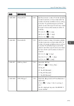


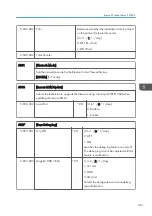


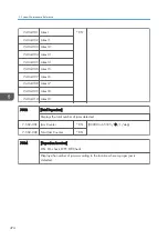


5-930-001 -
*ENG
-
Switches the meter-click charge mode on and off.
[0: OFF], [1: ON]
Important: Turn the main switch off/on after changing this setting.
OFF:
Meter charge mode disabled (default). This setting is for machines were the operator
is responsible for replacing the PCDU, the ITB unit, and the fusing unit.
Alert messages are displayed on the operation panel when the PCDU, the ITB unit,
and the fusing unit reach the limit of their yield.
ON:
Meter charge mode enabled. This setting is for machines which the service technician
has responsibility for servicing.
• Alert messages are not displayed when the PCDU, the ITB unit, and the fusing
unit reach the limits of their yield.
• If the setting of SP5-930-001 is set to "1 (enabled)", the settings of
SP5-930-010, -014 and -016 must be adjusted.
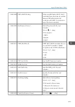
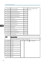
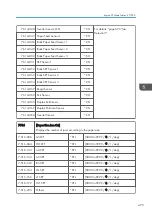
5-930-010 PCDU
*ENG
Displays or does not display the end display
for the PCDU. This SP is activated only when
the SP5930-001 is set to "1".
[0 or 1 / 1 / - /step]
0: OFF, 1: ON
5-930-014 Mid Trans Unit
*ENG
Displays or does not display the end display
for the ITB unit. This SP is activated only when
the SP5930-001 is set to "1".
[0 or 1 / 1 / - /step]
0: OFF, 1: ON
5-930-016 Fusing Unit
*ENG
Displays or does not display the end display
for the fusing unit. This SP is activated only
when the SP5930-001 is set to "1".
[0 or 1 / 1 / - /step]
0: OFF, 1: ON
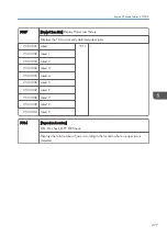
5987
[Mech. Counter]
Engine SP Mode Tables - SP5000
469
Summary of Contents for Z-P2
Page 1: ...Model Z P2 Machine Codes M257 Field Service Manual April 2015 ...
Page 2: ......
Page 30: ...1 Product Information 28 ...
Page 73: ...9 Install the securing holder E 10 Reassemble the machine Tray Heater 71 ...
Page 86: ...3 Preventive Maintenance 84 ...
Page 92: ...5 Left cover B Right Cover 1 Open the duplex unit A 4 Replacement and Adjustment 90 ...
Page 128: ...5 Open the upper cover A 4 Replacement and Adjustment 126 ...
Page 131: ...4 The left stay A x 4 5 Rear holder bracket A x 2 Image Transfer 129 ...
Page 139: ...3 Remove the two screws 4 ID sensor board bracket A x 1 Image Transfer 137 ...
Page 141: ...4 Exit the SP mode Image Transfer 139 ...
Page 146: ...2 Temperature Humidity sensor A x 1 x 1 4 Replacement and Adjustment 144 ...
Page 187: ...3 Bracket A x 1 4 Release the paper feed unit A x 1 Paper Feed 185 ...
Page 201: ...5 Inner left upper cover page 94 6 Paper exit unit holder A x 1 Paper Exit 199 ...
Page 211: ...6 Release the left arm A x 1 Duplex Unit 209 ...
Page 215: ...3 Duplex lower guide plate A 4 Duplex upper guide plate A x 7 Duplex Unit 213 ...
Page 220: ...8 Right and left arms A x 2 each 4 Replacement and Adjustment 218 ...
Page 221: ...9 Duplex By pass motor bracket with the frame A x 6 10 Guide plate A x 4 Duplex Unit 219 ...
Page 245: ...5 Disconnect the connector 6 Disconnect the six connectors x 1 Electrical Components 243 ...
Page 254: ...4 Replacement and Adjustment 252 ...
Page 564: ...5 System Maintenance Reference 562 ...
Page 637: ...Model Z P2 Machine Codes M257 Appendices February 2015 ...
Page 638: ......
Page 640: ...2 ...
Page 648: ...1 Appendix Specifications 10 ...
Page 652: ...MEMO 14 ...
Page 653: ...MEMO 15 ...
Page 654: ...MEMO 16 EN ...