


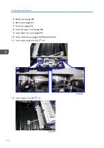


1.
Plug in and turn on the main power switch.
2.
Check that the settings of SP2-119-001, -002 and -003 are "0". If these settings are not
"0", execute "Recovery procedure for no replacement preparation of laser unit"
described above.
• If this step is not correctly done, an image problem may occur on printouts.
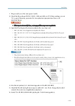
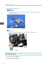
3.
Input the SP settings on the sheet provided with a new laser unit.
• SP2-101-001: Color Registration Adjustment for Black
• SP2-102-013, 015, 017, 019: Magnification Adjustment Main Beam Pitch Dot for each
color
• SP2-102-014, 016, 018, 020: Magnification Adjustment Main Beam Pitch Subdot for each
color
• SP2-102-001: Main Magnification for Black and Standard line speed
• SP2-102-002: Main Magnification for Black and Medium line speed
• SP2-102-003: Main Magnification for Black and Low line speed
• SP2-104-001 to -008: LD Initial Power Adjustment for each color
• The printed values [A] are different for each laser unit.
• If the SP settings shown above are not input correctly, it may cause color registration errors.
4.
Print the test pattern (14: 1-dot trimming pattern in the SP2-109-003).
5.
Check that the left and right trim margin is within 4 ± 1 mm. If not, change the standard
value for the main scan magnification adjustment.
6.
Select "0" with SP2-109-003 after printing the "1-dot trimming pattern.
Laser Optics
103
Summary of Contents for Z-P2
Page 1: ...Model Z P2 Machine Codes M257 Field Service Manual April 2015 ...
Page 2: ......
Page 30: ...1 Product Information 28 ...
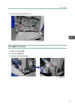
Page 73: ...9 Install the securing holder E 10 Reassemble the machine Tray Heater 71 ...
Page 86: ...3 Preventive Maintenance 84 ...
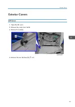
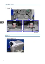
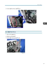
Page 92: ...5 Left cover B Right Cover 1 Open the duplex unit A 4 Replacement and Adjustment 90 ...
Page 128: ...5 Open the upper cover A 4 Replacement and Adjustment 126 ...
Page 131: ...4 The left stay A x 4 5 Rear holder bracket A x 2 Image Transfer 129 ...
Page 139: ...3 Remove the two screws 4 ID sensor board bracket A x 1 Image Transfer 137 ...
Page 141: ...4 Exit the SP mode Image Transfer 139 ...
Page 146: ...2 Temperature Humidity sensor A x 1 x 1 4 Replacement and Adjustment 144 ...
Page 187: ...3 Bracket A x 1 4 Release the paper feed unit A x 1 Paper Feed 185 ...
Page 201: ...5 Inner left upper cover page 94 6 Paper exit unit holder A x 1 Paper Exit 199 ...
Page 211: ...6 Release the left arm A x 1 Duplex Unit 209 ...
Page 215: ...3 Duplex lower guide plate A 4 Duplex upper guide plate A x 7 Duplex Unit 213 ...
Page 220: ...8 Right and left arms A x 2 each 4 Replacement and Adjustment 218 ...
Page 221: ...9 Duplex By pass motor bracket with the frame A x 6 10 Guide plate A x 4 Duplex Unit 219 ...
Page 245: ...5 Disconnect the connector 6 Disconnect the six connectors x 1 Electrical Components 243 ...
Page 254: ...4 Replacement and Adjustment 252 ...
Page 564: ...5 System Maintenance Reference 562 ...
Page 637: ...Model Z P2 Machine Codes M257 Appendices February 2015 ...
Page 638: ......
Page 640: ...2 ...
Page 648: ...1 Appendix Specifications 10 ...
Page 652: ...MEMO 14 ...
Page 653: ...MEMO 15 ...
Page 654: ...MEMO 16 EN ...