
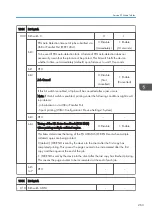


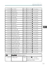


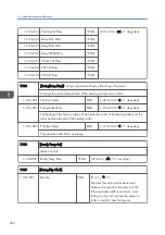


1105
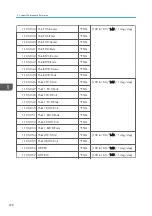
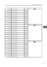
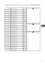
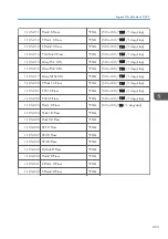
[Fusing Temp.] Fusing Temperature Adjustment
(Printing Mode, Roller Type, [Color], Simplex/Duplex)
Roller Type –> Center and Ends: Heating roller, P-Roller or PR –> Pressure roller
Paper Type -> Plain, Thin, Thick, OHP, Middle Thick, Special
Printing Mode -> S: Simplex, D: Duplex
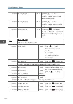
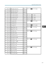
1-105-001 Fusing Ready Temp
*ENG
[100 to 180 / 160 / 1 deg/step]
Specifies the heating roller target temperature for the ready condition.
1-105-002 Fusing Ready: Offset
*ENG
[5 to 30 / 11 / 1 deg/step]
Specifies the subtracted temperature
of the heating roller for the fusing
reload start.
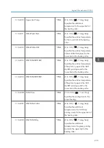
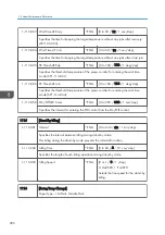
1-105-003 PR:RdyTrgt Temp.
*ENG
[50 to 160 / 120 / 1 deg/step]
Specifies the pressure roller target temperature for the ready condition.
1-105-007 P-Roll Ready Temp
*ENG
[0 to 150 / 20 / 1 deg/step]
Specifies the subtracted temperature of the pressure roller for the fusing reload start.
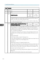
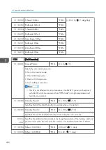
1-105-010 Stand-By: Center
* ENG
[50 to 180 / 160 / 1 deg/step]
Specifies the target center
temperature of the heating roller
(center) for the stand-by mode.
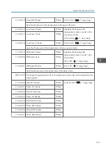
1-105-011 Stand-By: Ends
* ENG
[50 to 180 / 160 / 1 deg/step]
Specifies the target temperature of
the heating roller (ends) for the
stand-by mode.
1-105-012 Stand-By:P-Roller
* ENG
[50 to 160 / 140 / 1 deg/step]
Specifies the target temperature of the pressure roller for the stand-by mode.
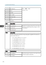
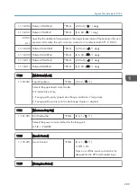
1-105-013 Panel Off: Center
* ENG
[50 to 180 / 140 / 1 deg /step]
Specifies the heating roller temperature (center) in the panel off mode.
1-105-014 Panel Off: Ends
* ENG
[50 to 180 / 140 / 1 deg /step]
Specifies the heating roller temperature (both ends) in the panel off mode.
5. System Maintenance Reference
276
Summary of Contents for Z-P2
Page 1: ...Model Z P2 Machine Codes M257 Field Service Manual April 2015 ...
Page 2: ......
Page 30: ...1 Product Information 28 ...
Page 73: ...9 Install the securing holder E 10 Reassemble the machine Tray Heater 71 ...
Page 86: ...3 Preventive Maintenance 84 ...
Page 92: ...5 Left cover B Right Cover 1 Open the duplex unit A 4 Replacement and Adjustment 90 ...
Page 128: ...5 Open the upper cover A 4 Replacement and Adjustment 126 ...
Page 131: ...4 The left stay A x 4 5 Rear holder bracket A x 2 Image Transfer 129 ...
Page 139: ...3 Remove the two screws 4 ID sensor board bracket A x 1 Image Transfer 137 ...
Page 141: ...4 Exit the SP mode Image Transfer 139 ...
Page 146: ...2 Temperature Humidity sensor A x 1 x 1 4 Replacement and Adjustment 144 ...
Page 187: ...3 Bracket A x 1 4 Release the paper feed unit A x 1 Paper Feed 185 ...
Page 201: ...5 Inner left upper cover page 94 6 Paper exit unit holder A x 1 Paper Exit 199 ...
Page 211: ...6 Release the left arm A x 1 Duplex Unit 209 ...
Page 215: ...3 Duplex lower guide plate A 4 Duplex upper guide plate A x 7 Duplex Unit 213 ...
Page 220: ...8 Right and left arms A x 2 each 4 Replacement and Adjustment 218 ...
Page 221: ...9 Duplex By pass motor bracket with the frame A x 6 10 Guide plate A x 4 Duplex Unit 219 ...
Page 245: ...5 Disconnect the connector 6 Disconnect the six connectors x 1 Electrical Components 243 ...
Page 254: ...4 Replacement and Adjustment 252 ...
Page 564: ...5 System Maintenance Reference 562 ...
Page 637: ...Model Z P2 Machine Codes M257 Appendices February 2015 ...
Page 638: ......
Page 640: ...2 ...
Page 648: ...1 Appendix Specifications 10 ...
Page 652: ...MEMO 14 ...
Page 653: ...MEMO 15 ...
Page 654: ...MEMO 16 EN ...