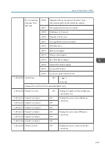


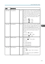


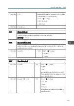


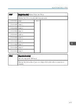

5-857-101 Start Date
*CTL
[- / 20120101 / 1 /step]
Sets start date of the debug log output.
5-857-102 End Date
*CTL
[- / 20371212 / 1 /step]
Sets end date of the debug log output.
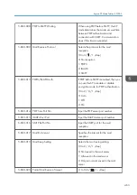
5-857-103 All Logs
*CTL
[Execute]
Obtains all debug logs.
5-857-104 Controller Logs
*CTL
[Execute]
Obtains controller debug log only.
5-857-105 Engine Debug Logs
*CTL
[Execute]
Obtains engine debug log only.
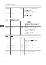
5-857-107 Opepanel Debug Logs
*CTL
[Execute]
Outputs the controller debug log to the
media inserted front I/F
5-857-120 Make LogTrace Dir
*CTL
[Execute]
Makes a folder for the log trace in the SD
card.
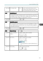
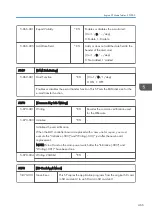
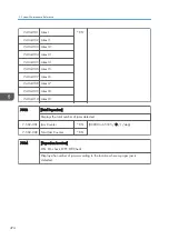
5860
[SMTP/POP3/IMAP4]
*CTL
-
5-860-002 SMTP Srvr Port no.
Input the SMTP server port number.
5-860-003 SMTP Auth
SMTP authentication enable/disable
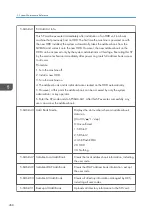
5-860-006 SMTP Auth Encryp
Encryption mode for SMTP authentication
enable/disable (Only valid if 5860 3 is
set to "enable")
5-860-007 POP before SMTP
Enable/disable POP before SMTP. If the
SMTP server does not have
authentication, you can enable POP
before SMTP, them POP authentication is
available (SP 5860 13)
5. System Maintenance Reference
462
Summary of Contents for Z-P2
Page 1: ...Model Z P2 Machine Codes M257 Field Service Manual April 2015 ...
Page 2: ......
Page 30: ...1 Product Information 28 ...
Page 73: ...9 Install the securing holder E 10 Reassemble the machine Tray Heater 71 ...
Page 86: ...3 Preventive Maintenance 84 ...
Page 92: ...5 Left cover B Right Cover 1 Open the duplex unit A 4 Replacement and Adjustment 90 ...
Page 128: ...5 Open the upper cover A 4 Replacement and Adjustment 126 ...
Page 131: ...4 The left stay A x 4 5 Rear holder bracket A x 2 Image Transfer 129 ...
Page 139: ...3 Remove the two screws 4 ID sensor board bracket A x 1 Image Transfer 137 ...
Page 141: ...4 Exit the SP mode Image Transfer 139 ...
Page 146: ...2 Temperature Humidity sensor A x 1 x 1 4 Replacement and Adjustment 144 ...
Page 187: ...3 Bracket A x 1 4 Release the paper feed unit A x 1 Paper Feed 185 ...
Page 201: ...5 Inner left upper cover page 94 6 Paper exit unit holder A x 1 Paper Exit 199 ...
Page 211: ...6 Release the left arm A x 1 Duplex Unit 209 ...
Page 215: ...3 Duplex lower guide plate A 4 Duplex upper guide plate A x 7 Duplex Unit 213 ...
Page 220: ...8 Right and left arms A x 2 each 4 Replacement and Adjustment 218 ...
Page 221: ...9 Duplex By pass motor bracket with the frame A x 6 10 Guide plate A x 4 Duplex Unit 219 ...
Page 245: ...5 Disconnect the connector 6 Disconnect the six connectors x 1 Electrical Components 243 ...
Page 254: ...4 Replacement and Adjustment 252 ...
Page 564: ...5 System Maintenance Reference 562 ...
Page 637: ...Model Z P2 Machine Codes M257 Appendices February 2015 ...
Page 638: ......
Page 640: ...2 ...
Page 648: ...1 Appendix Specifications 10 ...
Page 652: ...MEMO 14 ...
Page 653: ...MEMO 15 ...
Page 654: ...MEMO 16 EN ...