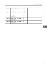


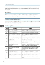


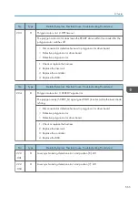


Type
Storage Timing
Destination (maximum storage
capacity)
Operation
panel debug
log
• When a controller SC occurs
• When saving by manual operation
with the Number keys and the Reset
key (Press “Reset”, “0”, "1” and “C”
(hold for 3 seconds))
• When the operation unit detects an
error
• When the operation panel detects an
error
Operation panel (400 MB /Up to
30 times)
When updating the firmware for the
operation panel, the debug logs are
erased.
8GB SD card
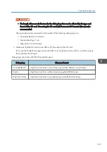
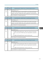
Debug logs are not saved when:
• Memory is being erased
• Data encryption equipment is being installed
• Firmware configuration is being changed
• There is a power outage (power cord disconnected accidentally).
• The machine is shut down normally but data write to the HDD cannot be completed. For example,
when shutdown starts immediately after a paper jam, or when the front door is opened and closed,
the machine needs about 5 sec. to save the debug log after the machine stops completely.
• Power supply to the HDD is off because of energy saving (engine OFF mode /STR mode)
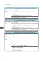
Operation Log Security
The following operation logs related to security are never saved.
• User ID
• Password
• IP address
• Telephone number
• Encryption key
• Transition to SP mode
The following operation logs are never saved.
• Number keys (0 to 9) on the operation panel
• Soft keyboard on the touch panel display
• External keyboard
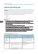
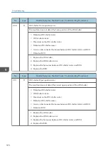
Capturing the Debug Logs
555
Summary of Contents for Z-P2
Page 1: ...Model Z P2 Machine Codes M257 Field Service Manual April 2015 ...
Page 2: ......
Page 30: ...1 Product Information 28 ...
Page 73: ...9 Install the securing holder E 10 Reassemble the machine Tray Heater 71 ...
Page 86: ...3 Preventive Maintenance 84 ...
Page 92: ...5 Left cover B Right Cover 1 Open the duplex unit A 4 Replacement and Adjustment 90 ...
Page 128: ...5 Open the upper cover A 4 Replacement and Adjustment 126 ...
Page 131: ...4 The left stay A x 4 5 Rear holder bracket A x 2 Image Transfer 129 ...
Page 139: ...3 Remove the two screws 4 ID sensor board bracket A x 1 Image Transfer 137 ...
Page 141: ...4 Exit the SP mode Image Transfer 139 ...
Page 146: ...2 Temperature Humidity sensor A x 1 x 1 4 Replacement and Adjustment 144 ...
Page 187: ...3 Bracket A x 1 4 Release the paper feed unit A x 1 Paper Feed 185 ...
Page 201: ...5 Inner left upper cover page 94 6 Paper exit unit holder A x 1 Paper Exit 199 ...
Page 211: ...6 Release the left arm A x 1 Duplex Unit 209 ...
Page 215: ...3 Duplex lower guide plate A 4 Duplex upper guide plate A x 7 Duplex Unit 213 ...
Page 220: ...8 Right and left arms A x 2 each 4 Replacement and Adjustment 218 ...
Page 221: ...9 Duplex By pass motor bracket with the frame A x 6 10 Guide plate A x 4 Duplex Unit 219 ...
Page 245: ...5 Disconnect the connector 6 Disconnect the six connectors x 1 Electrical Components 243 ...
Page 254: ...4 Replacement and Adjustment 252 ...
Page 564: ...5 System Maintenance Reference 562 ...
Page 637: ...Model Z P2 Machine Codes M257 Appendices February 2015 ...
Page 638: ......
Page 640: ...2 ...
Page 648: ...1 Appendix Specifications 10 ...
Page 652: ...MEMO 14 ...
Page 653: ...MEMO 15 ...
Page 654: ...MEMO 16 EN ...