
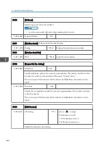


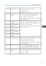

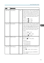


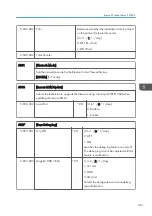


5-821-008 RCT Host URL Path
*CTL
Sets the host URL path of the destination for
processing calls to the @Remote service center.
255 bites characters allowed (0 to 255)
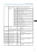
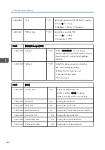
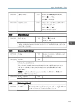
5824
[NV-RAM Upload]
Uploads the UP and SP mode data (except for counters and the serial number) from
the NVRAM to an SD card. For details, see the "NVRAM Data Upload/Download" in
the "System Maintenance Reference" of the Field Service Manual.
5-824-001 -
*CTL
-
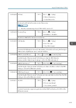
5825
[NV-RAM Download]
Downloads the UP and SP mode data from an SD card to the NVRAM. For details,
see the "NVRAM Data Upload/Download" in the "System Maintenance Reference"
of the Field Service Manual.
5-825-001 -
*CTL
-
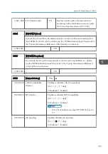
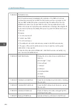
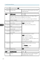
5828
[Network Setting]
*CTL
-
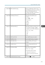
5-828-050 1284 Compatibility
(Centro)
Enables or disables 1284 Compatibility.
[0 or 1 / 1 / 1 / step]
0: Disabled, 1: Enabled
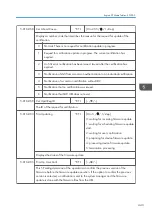
5-828-052 ECP (Centro)
Enables or disables ECP Compatibility.
[0 or 1 / 1 / 1 / step]
0: Disabled, 1: Enabled
• This SP is activated only when SP5-828-50 is set to
"1".
5-828-065 Job Spooling
Enables/disables Job Spooling.
[0 or 1 / 0 / 1 / step]
0: Disabled, 1: Enabled
Engine SP Mode Tables - SP5000
451
Summary of Contents for Z-P2
Page 1: ...Model Z P2 Machine Codes M257 Field Service Manual April 2015 ...
Page 2: ......
Page 30: ...1 Product Information 28 ...
Page 73: ...9 Install the securing holder E 10 Reassemble the machine Tray Heater 71 ...
Page 86: ...3 Preventive Maintenance 84 ...
Page 92: ...5 Left cover B Right Cover 1 Open the duplex unit A 4 Replacement and Adjustment 90 ...
Page 128: ...5 Open the upper cover A 4 Replacement and Adjustment 126 ...
Page 131: ...4 The left stay A x 4 5 Rear holder bracket A x 2 Image Transfer 129 ...
Page 139: ...3 Remove the two screws 4 ID sensor board bracket A x 1 Image Transfer 137 ...
Page 141: ...4 Exit the SP mode Image Transfer 139 ...
Page 146: ...2 Temperature Humidity sensor A x 1 x 1 4 Replacement and Adjustment 144 ...
Page 187: ...3 Bracket A x 1 4 Release the paper feed unit A x 1 Paper Feed 185 ...
Page 201: ...5 Inner left upper cover page 94 6 Paper exit unit holder A x 1 Paper Exit 199 ...
Page 211: ...6 Release the left arm A x 1 Duplex Unit 209 ...
Page 215: ...3 Duplex lower guide plate A 4 Duplex upper guide plate A x 7 Duplex Unit 213 ...
Page 220: ...8 Right and left arms A x 2 each 4 Replacement and Adjustment 218 ...
Page 221: ...9 Duplex By pass motor bracket with the frame A x 6 10 Guide plate A x 4 Duplex Unit 219 ...
Page 245: ...5 Disconnect the connector 6 Disconnect the six connectors x 1 Electrical Components 243 ...
Page 254: ...4 Replacement and Adjustment 252 ...
Page 564: ...5 System Maintenance Reference 562 ...
Page 637: ...Model Z P2 Machine Codes M257 Appendices February 2015 ...
Page 638: ......
Page 640: ...2 ...
Page 648: ...1 Appendix Specifications 10 ...
Page 652: ...MEMO 14 ...
Page 653: ...MEMO 15 ...
Page 654: ...MEMO 16 EN ...