


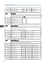


7-803-095 Page (%):Dev.U:Bk
ENG
[0 to 255 / - / 1 %/step]
7-803-096 Page (%):Dev.U:C
ENG
[0 to 255 / - / 1 %/step]
7-803-097 Page (%):Dev.U:M
ENG
[0 to 255 / - / 1 %/step]
7-803-098 Page (%):Dev.U:Y
ENG
[0 to 255 / - / 1 %/step]
7-803-103 Page (%):ITB Unit
ENG
[0 to 255 / - / 1 %/step]
7-803-104 Page(%):ITB Cln U
ENG
[0 to 255 / - / 1 %/step]
7-803-105 Page(%):Fus.Unit
ENG
[0 to 255 / - / 1 %/step]
7-803-106 Page(%):Fus.Roll
ENG
[0 to 255 / - / 1 %/step]
7-803-107 Page(%):Fus.Belt
ENG
[0 to 255 / - / 1 %/step]
7-803-108 Page(%):PTR Unit
ENG
[0 to 255 / - / 1 %/step]
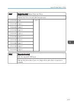
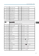
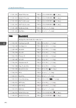
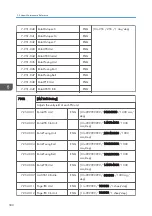
7804
[PM Counter Reset]
(Unit, [Color])
Clears the PM counter.
Press the Enter key after the machine asks "Execute?", which will store the PM counter
value in SP7-906 (PM Counter - Previous) and reset the value of the current PM
counter (SP7-803) to "0".
7-804-001 Paper
CTL
-
7-804-002 PCU: Bk
ENG
-
7-804-003 PCU: C
ENG
-
7-804-004 PCU: M
ENG
-
7-804-005 PCU: Y
ENG
-
7-804-006 PCU: All
ENG
-
7-804-007 Dev. Unit:Bk
ENG
-
7-804-008 Dev. Unit:C
ENG
-
7-804-009 Dev. Unit:M
ENG
-
7-804-010 Dev. Unit:Y
ENG
-
Engine SP Mode Tables - SP7000
485
Summary of Contents for Z-P2
Page 1: ...Model Z P2 Machine Codes M257 Field Service Manual April 2015 ...
Page 2: ......
Page 30: ...1 Product Information 28 ...
Page 73: ...9 Install the securing holder E 10 Reassemble the machine Tray Heater 71 ...
Page 86: ...3 Preventive Maintenance 84 ...
Page 92: ...5 Left cover B Right Cover 1 Open the duplex unit A 4 Replacement and Adjustment 90 ...
Page 128: ...5 Open the upper cover A 4 Replacement and Adjustment 126 ...
Page 131: ...4 The left stay A x 4 5 Rear holder bracket A x 2 Image Transfer 129 ...
Page 139: ...3 Remove the two screws 4 ID sensor board bracket A x 1 Image Transfer 137 ...
Page 141: ...4 Exit the SP mode Image Transfer 139 ...
Page 146: ...2 Temperature Humidity sensor A x 1 x 1 4 Replacement and Adjustment 144 ...
Page 187: ...3 Bracket A x 1 4 Release the paper feed unit A x 1 Paper Feed 185 ...
Page 201: ...5 Inner left upper cover page 94 6 Paper exit unit holder A x 1 Paper Exit 199 ...
Page 211: ...6 Release the left arm A x 1 Duplex Unit 209 ...
Page 215: ...3 Duplex lower guide plate A 4 Duplex upper guide plate A x 7 Duplex Unit 213 ...
Page 220: ...8 Right and left arms A x 2 each 4 Replacement and Adjustment 218 ...
Page 221: ...9 Duplex By pass motor bracket with the frame A x 6 10 Guide plate A x 4 Duplex Unit 219 ...
Page 245: ...5 Disconnect the connector 6 Disconnect the six connectors x 1 Electrical Components 243 ...
Page 254: ...4 Replacement and Adjustment 252 ...
Page 564: ...5 System Maintenance Reference 562 ...
Page 637: ...Model Z P2 Machine Codes M257 Appendices February 2015 ...
Page 638: ......
Page 640: ...2 ...
Page 648: ...1 Appendix Specifications 10 ...
Page 652: ...MEMO 14 ...
Page 653: ...MEMO 15 ...
Page 654: ...MEMO 16 EN ...