
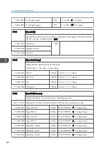


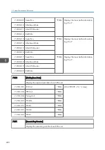


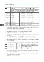


7-952-013 Page: Fusing Unit
ENG [1 to 999999 / 120000 / 1 sheet/step]
7-952-014 Page: Fusing Roll
ENG [1 to 999999 / 120000 / 1 sheet/step]
7-952-015 Page: Fusing Belt
ENG [1 to 999999 / 120000 / 1 sheet/step]
7-952-016 Page: PTR Unit
ENG [1 to 999999 / 180000/ 1 sheet/step]
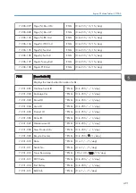
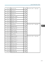
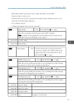
7-952-021 Day Thresh:PCU:Bk
ENG Adjusts the threshold day of the near end for
each PM unit.
[1 to 30 / 15 / 1 day/step]
These threshold days are used for @Remote
alarms.
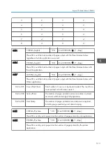
7-952-022 Day Thresh:PCU:C
ENG
7-952-023 Day Thresh:PCU:M
ENG
7-952-024 Day Thresh:PCU:Y
ENG
7-952-025 DayThrsh:Dev.U:Bk
ENG
7-952-026 DayThrsh:Dev.U:C
ENG
7-952-027 DayThrsh:Dev.U:M
ENG
7-952-028 DayThrsh:Dev.U:Y
ENG
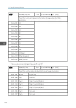
7-952-033 DayThresh:ITB U
ENG
7-952-034 DayThresh:ITB Cln
ENG
ENG
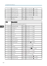
7-952-035 DayThresh:Fus.Unt
7-952-036 DayThresh:Fus.Rll
ENG
7-952-037 DayThresh:Fus.Blt
ENG
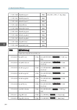
7-952-038 Rotation PCU Bk
ENG [0 to 999999999 / 0 / 1 mm/step]
7-952-039 Rotation PCU C
ENG
7-952-040 Rotation: PCU: M
ENG
7-952-041 Rotation: PCU: Y
ENG
7-952-042 Rotat:Dev.Unit:Bk
ENG
7-952-043 Rotat:Dev.Unit:C
ENG
7-952-044 Rotat:Dev.Unit:M
ENG
7-952-045 Rotat:Dev.Unit:Y
ENG
Engine SP Mode Tables - SP7000
501
Summary of Contents for Z-P2
Page 1: ...Model Z P2 Machine Codes M257 Field Service Manual April 2015 ...
Page 2: ......
Page 30: ...1 Product Information 28 ...
Page 73: ...9 Install the securing holder E 10 Reassemble the machine Tray Heater 71 ...
Page 86: ...3 Preventive Maintenance 84 ...
Page 92: ...5 Left cover B Right Cover 1 Open the duplex unit A 4 Replacement and Adjustment 90 ...
Page 128: ...5 Open the upper cover A 4 Replacement and Adjustment 126 ...
Page 131: ...4 The left stay A x 4 5 Rear holder bracket A x 2 Image Transfer 129 ...
Page 139: ...3 Remove the two screws 4 ID sensor board bracket A x 1 Image Transfer 137 ...
Page 141: ...4 Exit the SP mode Image Transfer 139 ...
Page 146: ...2 Temperature Humidity sensor A x 1 x 1 4 Replacement and Adjustment 144 ...
Page 187: ...3 Bracket A x 1 4 Release the paper feed unit A x 1 Paper Feed 185 ...
Page 201: ...5 Inner left upper cover page 94 6 Paper exit unit holder A x 1 Paper Exit 199 ...
Page 211: ...6 Release the left arm A x 1 Duplex Unit 209 ...
Page 215: ...3 Duplex lower guide plate A 4 Duplex upper guide plate A x 7 Duplex Unit 213 ...
Page 220: ...8 Right and left arms A x 2 each 4 Replacement and Adjustment 218 ...
Page 221: ...9 Duplex By pass motor bracket with the frame A x 6 10 Guide plate A x 4 Duplex Unit 219 ...
Page 245: ...5 Disconnect the connector 6 Disconnect the six connectors x 1 Electrical Components 243 ...
Page 254: ...4 Replacement and Adjustment 252 ...
Page 564: ...5 System Maintenance Reference 562 ...
Page 637: ...Model Z P2 Machine Codes M257 Appendices February 2015 ...
Page 638: ......
Page 640: ...2 ...
Page 648: ...1 Appendix Specifications 10 ...
Page 652: ...MEMO 14 ...
Page 653: ...MEMO 15 ...
Page 654: ...MEMO 16 EN ...