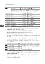


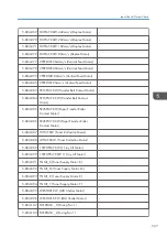


8801
Toner Remain
*CTL
[0 to 100/ 0 / 1 /step]
These SPs display the percent of toner remaining for each color. This SP allows the
user to check the toner supply at any time.
Note: This precise method of measuring remaining toner supply (1% steps) is better
than other machines in the market that can only measure in increments of 10 (10%
steps).
8-801-001 K
8-801-002 Y
8-801-003 M
8-801-004 C
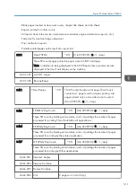
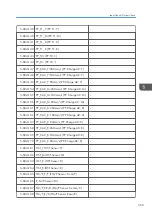
8811
Eco Counter
Displays the counter for each mode.
8-811-001 Eco Total
*CTL
[0 to 99999999 / 0 / 1/step]
8-811-002 Color
*CTL
8-811-003 Full Color
*CTL
8-811-004 Duplex
*CTL
8-811-005 Combine
*CTL
8-811-006 Color (%)
*CTL
[0 to 100 / 0 / 1%/step]
8-811-007 Full Color (%)
*CTL
8-811-008 Duplex (%)
*CTL
8-811-009 Combine (%)
*CTL
8-811-010 Paper Cut (%)
*CTL
5. System Maintenance Reference
524
Summary of Contents for Z-P2
Page 1: ...Model Z P2 Machine Codes M257 Field Service Manual April 2015 ...
Page 2: ......
Page 30: ...1 Product Information 28 ...
Page 73: ...9 Install the securing holder E 10 Reassemble the machine Tray Heater 71 ...
Page 86: ...3 Preventive Maintenance 84 ...
Page 92: ...5 Left cover B Right Cover 1 Open the duplex unit A 4 Replacement and Adjustment 90 ...
Page 128: ...5 Open the upper cover A 4 Replacement and Adjustment 126 ...
Page 131: ...4 The left stay A x 4 5 Rear holder bracket A x 2 Image Transfer 129 ...
Page 139: ...3 Remove the two screws 4 ID sensor board bracket A x 1 Image Transfer 137 ...
Page 141: ...4 Exit the SP mode Image Transfer 139 ...
Page 146: ...2 Temperature Humidity sensor A x 1 x 1 4 Replacement and Adjustment 144 ...
Page 187: ...3 Bracket A x 1 4 Release the paper feed unit A x 1 Paper Feed 185 ...
Page 201: ...5 Inner left upper cover page 94 6 Paper exit unit holder A x 1 Paper Exit 199 ...
Page 211: ...6 Release the left arm A x 1 Duplex Unit 209 ...
Page 215: ...3 Duplex lower guide plate A 4 Duplex upper guide plate A x 7 Duplex Unit 213 ...
Page 220: ...8 Right and left arms A x 2 each 4 Replacement and Adjustment 218 ...
Page 221: ...9 Duplex By pass motor bracket with the frame A x 6 10 Guide plate A x 4 Duplex Unit 219 ...
Page 245: ...5 Disconnect the connector 6 Disconnect the six connectors x 1 Electrical Components 243 ...
Page 254: ...4 Replacement and Adjustment 252 ...
Page 564: ...5 System Maintenance Reference 562 ...
Page 637: ...Model Z P2 Machine Codes M257 Appendices February 2015 ...
Page 638: ......
Page 640: ...2 ...
Page 648: ...1 Appendix Specifications 10 ...
Page 652: ...MEMO 14 ...
Page 653: ...MEMO 15 ...
Page 654: ...MEMO 16 EN ...