


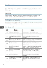


Capturing the Debug Logs
Overview
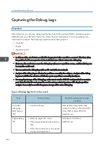
With this feature, you can save debug logs that are stored in the machine (HDD or operation panel or
8GB SD Card) on an SD card. This function allows the Customer Engineer to save and retrieve error
information for analysis. The Capturing Log feature saves debug logs for:
• Controller
• Engine
• Operation panel
• In older models, a technician enabled the logging tool after a problem occurred. After that, when
the problem had been reproduced, the technician was able to retrieve the debug log.
• However, this new feature saves the debug logs whenever a problem occurs, and then this log can
be saved to an SD card.
• You can retrieve the debug logs with an SD card without a network.
• Analysis of the debug log is effective for problems caused by the software. Analysis of the debug
log is not valid for the selection of defective parts or problems caused by hardware.
• For everyday storage of the debug log, make sure to use the 8GB SD card provided as a service
part. Note that this SD card cannot be used to retrieve selected portions of the log for problem
analysis. It can only be used for long-term storage of the entire debug log.
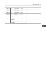
Types of debug logs that can be saved
Type
Storage Timing
Destination (maximum storage
capacity)
Controller
debug log
(GW debug
log)
• Saved at all times
HDD (4 GB). Compressed when
written to an SD card from the HDD
(from 4 GB to about 300 MB),
8GB SD card
Engine debug
log
• When an engine SC occurs
• When paper feeding/output stop by
jams
• When the machine doors are opened
during normal operation
HDD (Up to 300 times),
8GB SD card
5. System Maintenance Reference
554
Summary of Contents for Z-P2
Page 1: ...Model Z P2 Machine Codes M257 Field Service Manual April 2015 ...
Page 2: ......
Page 30: ...1 Product Information 28 ...
Page 73: ...9 Install the securing holder E 10 Reassemble the machine Tray Heater 71 ...
Page 86: ...3 Preventive Maintenance 84 ...
Page 92: ...5 Left cover B Right Cover 1 Open the duplex unit A 4 Replacement and Adjustment 90 ...
Page 128: ...5 Open the upper cover A 4 Replacement and Adjustment 126 ...
Page 131: ...4 The left stay A x 4 5 Rear holder bracket A x 2 Image Transfer 129 ...
Page 139: ...3 Remove the two screws 4 ID sensor board bracket A x 1 Image Transfer 137 ...
Page 141: ...4 Exit the SP mode Image Transfer 139 ...
Page 146: ...2 Temperature Humidity sensor A x 1 x 1 4 Replacement and Adjustment 144 ...
Page 187: ...3 Bracket A x 1 4 Release the paper feed unit A x 1 Paper Feed 185 ...
Page 201: ...5 Inner left upper cover page 94 6 Paper exit unit holder A x 1 Paper Exit 199 ...
Page 211: ...6 Release the left arm A x 1 Duplex Unit 209 ...
Page 215: ...3 Duplex lower guide plate A 4 Duplex upper guide plate A x 7 Duplex Unit 213 ...
Page 220: ...8 Right and left arms A x 2 each 4 Replacement and Adjustment 218 ...
Page 221: ...9 Duplex By pass motor bracket with the frame A x 6 10 Guide plate A x 4 Duplex Unit 219 ...
Page 245: ...5 Disconnect the connector 6 Disconnect the six connectors x 1 Electrical Components 243 ...
Page 254: ...4 Replacement and Adjustment 252 ...
Page 564: ...5 System Maintenance Reference 562 ...
Page 637: ...Model Z P2 Machine Codes M257 Appendices February 2015 ...
Page 638: ......
Page 640: ...2 ...
Page 648: ...1 Appendix Specifications 10 ...
Page 652: ...MEMO 14 ...
Page 653: ...MEMO 15 ...
Page 654: ...MEMO 16 EN ...