


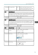

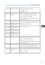


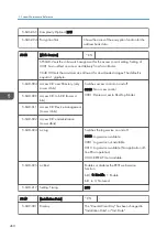


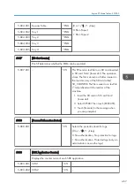


5-846-041 Fill Addr Acl Info.
This SP must be executed immediately after installation of an HDD unit in a basic
machine that previously had no HDD. The first time the machine is powered on with
the new HDD installed, the system automatically takes the address book from the
NVRAM and writes it onto the new HDD. However, the new address book on the
HDD can be accessed only by the system administrator at this stage. Executing this SP
by the service technician immediately after power on grants full address book access
to all users.
Procedure
1. Turn the machine off.
2. Install a new HDD.
3. Turn the machine on.
4. The address book and its initial data are created on the HDD automatically.
5. However, at this point the address book can be accessed by only the system
administrator or key operator.
6. Enter the SP mode and do SP5846-041. After this SP executes successfully, any
user can access the address book.
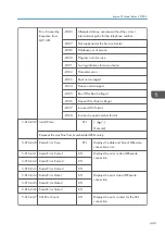
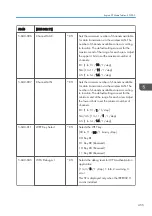
5-846-043 Addr Book Media
Displays the slot number where an address book
data is in.
[0 to 30 / - /1 /step]
0: Unconfirmed
1: SD Slot 1
2: SD Slot 2
4: USB Flash ROM
20: HDD
30: Nothing
5-846-047 Initialize Local Addr Book
Clears the local address book information, including
the user code.
5-846-049 Initialize LDAP Addr Book
Clears the LDAP address book information, except
the user code.
5-846-050 Initialize All Addr Book
Clears all directory information managed by UCS,
including all user codes.
5-846-051 Backup All Addr Book
Uploads all directory information to the SD card.
5. System Maintenance Reference
458
Summary of Contents for Z-P2
Page 1: ...Model Z P2 Machine Codes M257 Field Service Manual April 2015 ...
Page 2: ......
Page 30: ...1 Product Information 28 ...
Page 73: ...9 Install the securing holder E 10 Reassemble the machine Tray Heater 71 ...
Page 86: ...3 Preventive Maintenance 84 ...
Page 92: ...5 Left cover B Right Cover 1 Open the duplex unit A 4 Replacement and Adjustment 90 ...
Page 128: ...5 Open the upper cover A 4 Replacement and Adjustment 126 ...
Page 131: ...4 The left stay A x 4 5 Rear holder bracket A x 2 Image Transfer 129 ...
Page 139: ...3 Remove the two screws 4 ID sensor board bracket A x 1 Image Transfer 137 ...
Page 141: ...4 Exit the SP mode Image Transfer 139 ...
Page 146: ...2 Temperature Humidity sensor A x 1 x 1 4 Replacement and Adjustment 144 ...
Page 187: ...3 Bracket A x 1 4 Release the paper feed unit A x 1 Paper Feed 185 ...
Page 201: ...5 Inner left upper cover page 94 6 Paper exit unit holder A x 1 Paper Exit 199 ...
Page 211: ...6 Release the left arm A x 1 Duplex Unit 209 ...
Page 215: ...3 Duplex lower guide plate A 4 Duplex upper guide plate A x 7 Duplex Unit 213 ...
Page 220: ...8 Right and left arms A x 2 each 4 Replacement and Adjustment 218 ...
Page 221: ...9 Duplex By pass motor bracket with the frame A x 6 10 Guide plate A x 4 Duplex Unit 219 ...
Page 245: ...5 Disconnect the connector 6 Disconnect the six connectors x 1 Electrical Components 243 ...
Page 254: ...4 Replacement and Adjustment 252 ...
Page 564: ...5 System Maintenance Reference 562 ...
Page 637: ...Model Z P2 Machine Codes M257 Appendices February 2015 ...
Page 638: ......
Page 640: ...2 ...
Page 648: ...1 Appendix Specifications 10 ...
Page 652: ...MEMO 14 ...
Page 653: ...MEMO 15 ...
Page 654: ...MEMO 16 EN ...