


11.
Turn the main switch off and on.
12.
Copy the data from the SD card to the NVRAM (SP5-825-001) if you have successfully
copied them to the SD card.
13.
Turn the main switch off. Then remove the SD card from SD card slot 2.
14.
Turn the main switch on.
15.
Specify the SP and UP mode settings.
16.
Do the process control self-check.
NVRAM on the Controller
After Replacement of a Defective NVRAM
1.
You need the factory settings sheet provided with the machine.
2.
Turn the power on, enter the SP mode, and then do the factory settings.
3.
Re-install security settings as required.
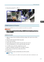
NVRAM Upload and Download
1.
Make sure that you have the SMC report (factory settings). This report comes with the
machine.
2.
Output the SMC data (SP5-990-001) if possible.
3.
Turn the main switch off. Then unplug the power cord.
4.
Turn the main switch on.
5.
Copy the NVRAM data (SP5-824-001) and the address book data in the HDD
(SP5846-051) to an SD card if possible.
• An error message appears if local user information cannot be stored in an SD card because
the capacity is not enough.
• You cannot do this procedure if the SD card is write-protected.
6.
Enter SP mode. Then print out the SMC reports (SP5-990-001) if possible.
7.
Turn off the main switch. Then unplug the power cord.
8.
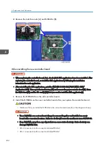
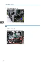
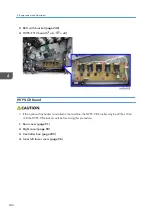
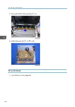
Replace the NVRAM on the controller. Then reassemble the machine.
9.
Plug in the power cord. Then turn the main switch on.
10.
Check if the serial number appears on the operation panel (SP5-811-002). Input the serial
number if it does not appear. (Contact your supervisor about this setting.)
4. Replacement and Adjustment
246
Summary of Contents for Z-P2
Page 1: ...Model Z P2 Machine Codes M257 Field Service Manual April 2015 ...
Page 2: ......
Page 30: ...1 Product Information 28 ...
Page 73: ...9 Install the securing holder E 10 Reassemble the machine Tray Heater 71 ...
Page 86: ...3 Preventive Maintenance 84 ...
Page 92: ...5 Left cover B Right Cover 1 Open the duplex unit A 4 Replacement and Adjustment 90 ...
Page 128: ...5 Open the upper cover A 4 Replacement and Adjustment 126 ...
Page 131: ...4 The left stay A x 4 5 Rear holder bracket A x 2 Image Transfer 129 ...
Page 139: ...3 Remove the two screws 4 ID sensor board bracket A x 1 Image Transfer 137 ...
Page 141: ...4 Exit the SP mode Image Transfer 139 ...
Page 146: ...2 Temperature Humidity sensor A x 1 x 1 4 Replacement and Adjustment 144 ...
Page 187: ...3 Bracket A x 1 4 Release the paper feed unit A x 1 Paper Feed 185 ...
Page 201: ...5 Inner left upper cover page 94 6 Paper exit unit holder A x 1 Paper Exit 199 ...
Page 211: ...6 Release the left arm A x 1 Duplex Unit 209 ...
Page 215: ...3 Duplex lower guide plate A 4 Duplex upper guide plate A x 7 Duplex Unit 213 ...
Page 220: ...8 Right and left arms A x 2 each 4 Replacement and Adjustment 218 ...
Page 221: ...9 Duplex By pass motor bracket with the frame A x 6 10 Guide plate A x 4 Duplex Unit 219 ...
Page 245: ...5 Disconnect the connector 6 Disconnect the six connectors x 1 Electrical Components 243 ...
Page 254: ...4 Replacement and Adjustment 252 ...
Page 564: ...5 System Maintenance Reference 562 ...
Page 637: ...Model Z P2 Machine Codes M257 Appendices February 2015 ...
Page 638: ......
Page 640: ...2 ...
Page 648: ...1 Appendix Specifications 10 ...
Page 652: ...MEMO 14 ...
Page 653: ...MEMO 15 ...
Page 654: ...MEMO 16 EN ...