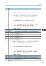

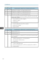


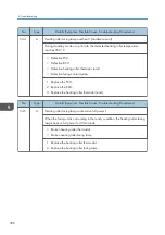


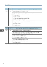


No.
Type
Details (Symptom, Possible Cause, Troubleshooting Procedures)
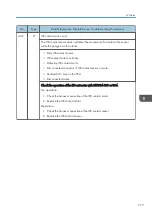
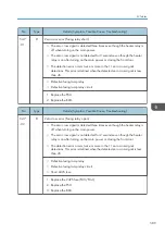
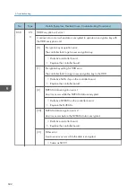
542
A
Heating roller warm-up error 1
• After the main switch is turned on or the cover is closed, the increment of the
heating roller temperature per 10 seconds is 30°C or less. If this condition is
detected five times consecutively, SC 542 is defined.
• The heating roller temperature does not reach 100°C for 15 seconds after
the heating lamp on.
• The heating roller temperature does not reach the ready temperature while
60 seconds after the heating lamp on.
• The center temperature of the heating roller does not reach the ready
temperature for 30 seconds after the edge temperature of the heating roller
has reached the ready temperature.
• Dirty or defective thermopile
• Defective thermopile.
• Trash on the surface of the thermopile lens.
• Defected thermistor.
• Input voltage is over guaranteed value
• Defective heating roller lamp
1. Check if the thermopile is firmly connected.
2. Clean the surface of the thermopile lens.
3. Test the conductance for the thermopile and the heating roller
4. Replace the thermopile.
5. Replace the heating roller lamp.
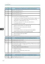
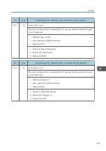
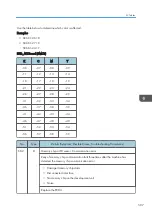
No.
Type
Details (Symptom, Possible Cause, Troubleshooting Procedures)
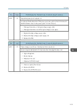
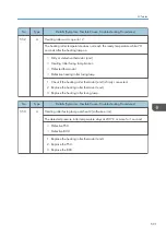
543
A
Heating roller fusing lamp overheat 1 (software error)
The detected fusing temperature stays at 245°C for 1 second.
• Defective PSU
• Defective BCU
1. Replace the PSU.
2. Replace the BCU.
SC Tables
587
Summary of Contents for Z-P2
Page 1: ...Model Z P2 Machine Codes M257 Field Service Manual April 2015 ...
Page 2: ......
Page 30: ...1 Product Information 28 ...
Page 73: ...9 Install the securing holder E 10 Reassemble the machine Tray Heater 71 ...
Page 86: ...3 Preventive Maintenance 84 ...
Page 92: ...5 Left cover B Right Cover 1 Open the duplex unit A 4 Replacement and Adjustment 90 ...
Page 128: ...5 Open the upper cover A 4 Replacement and Adjustment 126 ...
Page 131: ...4 The left stay A x 4 5 Rear holder bracket A x 2 Image Transfer 129 ...
Page 139: ...3 Remove the two screws 4 ID sensor board bracket A x 1 Image Transfer 137 ...
Page 141: ...4 Exit the SP mode Image Transfer 139 ...
Page 146: ...2 Temperature Humidity sensor A x 1 x 1 4 Replacement and Adjustment 144 ...
Page 187: ...3 Bracket A x 1 4 Release the paper feed unit A x 1 Paper Feed 185 ...
Page 201: ...5 Inner left upper cover page 94 6 Paper exit unit holder A x 1 Paper Exit 199 ...
Page 211: ...6 Release the left arm A x 1 Duplex Unit 209 ...
Page 215: ...3 Duplex lower guide plate A 4 Duplex upper guide plate A x 7 Duplex Unit 213 ...
Page 220: ...8 Right and left arms A x 2 each 4 Replacement and Adjustment 218 ...
Page 221: ...9 Duplex By pass motor bracket with the frame A x 6 10 Guide plate A x 4 Duplex Unit 219 ...
Page 245: ...5 Disconnect the connector 6 Disconnect the six connectors x 1 Electrical Components 243 ...
Page 254: ...4 Replacement and Adjustment 252 ...
Page 564: ...5 System Maintenance Reference 562 ...
Page 637: ...Model Z P2 Machine Codes M257 Appendices February 2015 ...
Page 638: ......
Page 640: ...2 ...
Page 648: ...1 Appendix Specifications 10 ...
Page 652: ...MEMO 14 ...
Page 653: ...MEMO 15 ...
Page 654: ...MEMO 16 EN ...