
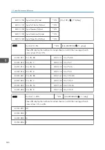


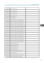

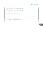


5-804-139 PP_T1_Y (PP: T1: Y)
-
5-804-140 PP_T1_M (PP: T1: M)
-
5-804-141 PP_T1_C (PP: T1: C)
-
5-804-142 PP_T1_K (PP: T1: K)
-
5-804-143 PP_T2+ (PP: T2: +)
-
5-804-144 PP_T2- (PP: T2: -)
-
5-804-147 PP_CAC_Y:260mm/s (PP: Charge AC: Y)
-
5-804-148 PP_CAC_Y:182mm/s (PP: Charge AC: Y)
-
5-804-149 PP_CAC_Y:85mm/s (PP: Charge AC: Y)
-
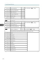
5-804-154 PP_CAC_M:260mm/s (PP: Charge AC: M)
-
5-804-155 PP_CAC_M:182mm/s (PP: Charge AC: M)
-
5-804-156 PP_CAC_M:85mm/s (PP: Charge AC: M)
-
5-804-161 PP_CAC_C:260mm/s (PP: Charge AC: C)
-
5-804-162 PP_CAC_C:182mm/s (PP: Charge AC: C)
-
5-804-163 PP_CAC_C:85mm/s (PP: Charge AC: C)
-
5-804-168 PP_CAC_K:260mm/s (PP: Charge AC: K)
-
5-804-169 PP_CAC_K:182mm/s (PP: Charge AC: K)
-
5-804-170 PP_CAC_K:85mm/s (PP: Charge AC: K)
-
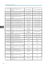
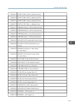
5-804-181 HST_Y (HST Sensor: Y)
-
5-804-182 HST_M (HST Sensor: M)
-
5-804-183 HST_C (HST Sensor: C)
-
5-804-184 HST_K (HST Sensor: K)
-
5-804-185 TM/P_F/Y (TM/P Sensor: Front/Y)
-
5-804-186 P_M (P Sensor: M)
-
5-804-187 TM/P_CE/C (TM/P Sensor: Center/C)
-
5-804-188 TM/P_R/K (TM/P Sensor: Rear/K)
-
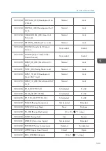
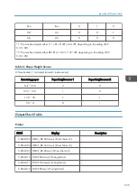
Input Check/ Output Check
539
Summary of Contents for Z-P2
Page 1: ...Model Z P2 Machine Codes M257 Field Service Manual April 2015 ...
Page 2: ......
Page 30: ...1 Product Information 28 ...
Page 73: ...9 Install the securing holder E 10 Reassemble the machine Tray Heater 71 ...
Page 86: ...3 Preventive Maintenance 84 ...
Page 92: ...5 Left cover B Right Cover 1 Open the duplex unit A 4 Replacement and Adjustment 90 ...
Page 128: ...5 Open the upper cover A 4 Replacement and Adjustment 126 ...
Page 131: ...4 The left stay A x 4 5 Rear holder bracket A x 2 Image Transfer 129 ...
Page 139: ...3 Remove the two screws 4 ID sensor board bracket A x 1 Image Transfer 137 ...
Page 141: ...4 Exit the SP mode Image Transfer 139 ...
Page 146: ...2 Temperature Humidity sensor A x 1 x 1 4 Replacement and Adjustment 144 ...
Page 187: ...3 Bracket A x 1 4 Release the paper feed unit A x 1 Paper Feed 185 ...
Page 201: ...5 Inner left upper cover page 94 6 Paper exit unit holder A x 1 Paper Exit 199 ...
Page 211: ...6 Release the left arm A x 1 Duplex Unit 209 ...
Page 215: ...3 Duplex lower guide plate A 4 Duplex upper guide plate A x 7 Duplex Unit 213 ...
Page 220: ...8 Right and left arms A x 2 each 4 Replacement and Adjustment 218 ...
Page 221: ...9 Duplex By pass motor bracket with the frame A x 6 10 Guide plate A x 4 Duplex Unit 219 ...
Page 245: ...5 Disconnect the connector 6 Disconnect the six connectors x 1 Electrical Components 243 ...
Page 254: ...4 Replacement and Adjustment 252 ...
Page 564: ...5 System Maintenance Reference 562 ...
Page 637: ...Model Z P2 Machine Codes M257 Appendices February 2015 ...
Page 638: ......
Page 640: ...2 ...
Page 648: ...1 Appendix Specifications 10 ...
Page 652: ...MEMO 14 ...
Page 653: ...MEMO 15 ...
Page 654: ...MEMO 16 EN ...