


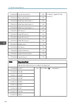
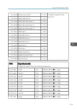


-031 to -048 Displays the number of revolutions of motors or clutches for each current
maintenance unit.
When a unit is replaced, the machine automatically detects that the new unit is
installed. Then, the current PM counter value is automatically moved to the PM
Counter - Previous (SP7-906-31 to 49) and is reset to "0". The total number of
revolutions made with the last unit replaced can be checked with SP7-906-31 to 49.
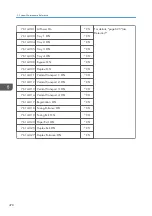
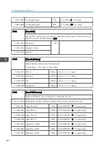
7-803-031 Rotation: PCU: Bk
ENG
[0 to 999999999 / - / 1 mm/step]
7-803-032 Rotation: PCU: C
ENG
[0 to 999999999 / - / 1 mm/step]
7-803-033 Rotation: PCU: M
ENG
[0 to 999999999 / - / 1 mm/step]
7-803-034 Rotation: PCU: Y
ENG
[0 to 999999999 / - / 1 mm/step]
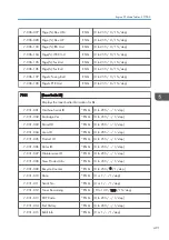
7-803-035 Rotat:Dev.Unit:Bk
ENG
[0 to 999999999 / - / 1 mm/step]
7-803-036 Rotat:Dev.Unit:C
ENG
[0 to 999999999 / - / 1 mm/step]
7-803-037 Rotat:Dev.Unit:M
ENG
[0 to 999999999 / - / 1 mm/step]
7-803-038 Rotat:Dev.Unit:Y
ENG
[0 to 999999999 / - / 1 mm/step]
7-803-043 Rotation:ITB Unit
ENG
[0 to 999999999 / - / 1 mm/step]
7-803-044 Rotat:ITBCln.Unit
ENG
[0 to 999999999 / - / 1 mm/step]
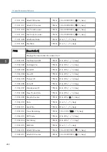
7-803-045 Rotat:Fusing Unit
ENG
[0 to 999999999 / - / 1 mm/step]
7-803-046 Rotat:Fus.Roller
ENG
[0 to 999999999 / - / 1 mm/step]
7-803-047 Rotat:Fusing Belt
ENG
[0 to 999999999 / - / 1 mg/step]
7-803-048 Rotation PTR Unit
ENG
[0 to 999999999 / - / 1 mm/step]
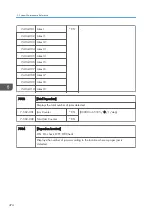
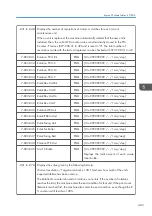
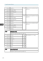
7-803-049 Msr TC Bottle
ENG
[0 to 999999999 / - / 1 mg/step ]
Displays the total amount of each waste
toner bottle.
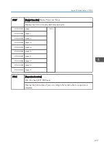
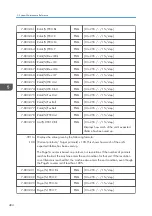
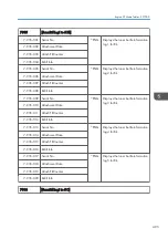
-061 to -078 Displays the value given by the following formula:
(Current revolution / Target revolution) x 100. This shows how much of the unit's
expected lifetime has been used up.
The Rotation% counter is based on rotations, not prints. If the number of rotations
reaches the limit, the machine enters the end condition for that unit. If the print count
lifetime is reached first, the machine also enters the end condition, even though the R
% counter is still less than 100%.
Engine SP Mode Tables - SP7000
483
Summary of Contents for Z-P2
Page 1: ...Model Z P2 Machine Codes M257 Field Service Manual April 2015 ...
Page 2: ......
Page 30: ...1 Product Information 28 ...
Page 73: ...9 Install the securing holder E 10 Reassemble the machine Tray Heater 71 ...
Page 86: ...3 Preventive Maintenance 84 ...
Page 92: ...5 Left cover B Right Cover 1 Open the duplex unit A 4 Replacement and Adjustment 90 ...
Page 128: ...5 Open the upper cover A 4 Replacement and Adjustment 126 ...
Page 131: ...4 The left stay A x 4 5 Rear holder bracket A x 2 Image Transfer 129 ...
Page 139: ...3 Remove the two screws 4 ID sensor board bracket A x 1 Image Transfer 137 ...
Page 141: ...4 Exit the SP mode Image Transfer 139 ...
Page 146: ...2 Temperature Humidity sensor A x 1 x 1 4 Replacement and Adjustment 144 ...
Page 187: ...3 Bracket A x 1 4 Release the paper feed unit A x 1 Paper Feed 185 ...
Page 201: ...5 Inner left upper cover page 94 6 Paper exit unit holder A x 1 Paper Exit 199 ...
Page 211: ...6 Release the left arm A x 1 Duplex Unit 209 ...
Page 215: ...3 Duplex lower guide plate A 4 Duplex upper guide plate A x 7 Duplex Unit 213 ...
Page 220: ...8 Right and left arms A x 2 each 4 Replacement and Adjustment 218 ...
Page 221: ...9 Duplex By pass motor bracket with the frame A x 6 10 Guide plate A x 4 Duplex Unit 219 ...
Page 245: ...5 Disconnect the connector 6 Disconnect the six connectors x 1 Electrical Components 243 ...
Page 254: ...4 Replacement and Adjustment 252 ...
Page 564: ...5 System Maintenance Reference 562 ...
Page 637: ...Model Z P2 Machine Codes M257 Appendices February 2015 ...
Page 638: ......
Page 640: ...2 ...
Page 648: ...1 Appendix Specifications 10 ...
Page 652: ...MEMO 14 ...
Page 653: ...MEMO 15 ...
Page 654: ...MEMO 16 EN ...