


5. System Maintenance Reference
Service Program Mode
• Make sure that the data-in LED is not on before you go into the SP mode. This LED indicates that
some data is coming to the machine. When the LED is on, wait for the printer to process the data.
Service Mode Operation
• The Service Program Mode is for use by service representatives only so that they can properly
maintain product quality. If this mode is used by anyone other than service representatives for any
reason, data might be deleted or settings might be changed. In such case, product quality cannot
be guaranteed any more.
Accessing the Required Program
Use the "Up/Down arrow" keys to scroll through the menu listing.
1. Service: Controller service modes
2. Engine: Engine service modes
3. End: Exit service mode
To select an item, press the "OK" key. Then the sub-menu shows.
Scroll through the sub menu items using the " " keys.
To go back to a higher level, press the "Escape" key.
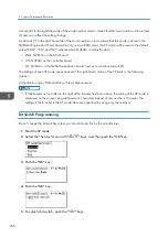
Inputting a Value or Setting for a Service Program
Enter the required program mode as explained above. The setting appearing on the display is the
current setting.
Select the required setting using the " " keys, then press the "OK" key. The previous value remains if
the "OK" key is not pressed.
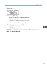
Exiting Service Mode
Select "End" from the service mode main menu, then press the "OK" key.
253
Summary of Contents for Z-P2
Page 1: ...Model Z P2 Machine Codes M257 Field Service Manual April 2015 ...
Page 2: ......
Page 30: ...1 Product Information 28 ...
Page 73: ...9 Install the securing holder E 10 Reassemble the machine Tray Heater 71 ...
Page 86: ...3 Preventive Maintenance 84 ...
Page 92: ...5 Left cover B Right Cover 1 Open the duplex unit A 4 Replacement and Adjustment 90 ...
Page 128: ...5 Open the upper cover A 4 Replacement and Adjustment 126 ...
Page 131: ...4 The left stay A x 4 5 Rear holder bracket A x 2 Image Transfer 129 ...
Page 139: ...3 Remove the two screws 4 ID sensor board bracket A x 1 Image Transfer 137 ...
Page 141: ...4 Exit the SP mode Image Transfer 139 ...
Page 146: ...2 Temperature Humidity sensor A x 1 x 1 4 Replacement and Adjustment 144 ...
Page 187: ...3 Bracket A x 1 4 Release the paper feed unit A x 1 Paper Feed 185 ...
Page 201: ...5 Inner left upper cover page 94 6 Paper exit unit holder A x 1 Paper Exit 199 ...
Page 211: ...6 Release the left arm A x 1 Duplex Unit 209 ...
Page 215: ...3 Duplex lower guide plate A 4 Duplex upper guide plate A x 7 Duplex Unit 213 ...
Page 220: ...8 Right and left arms A x 2 each 4 Replacement and Adjustment 218 ...
Page 221: ...9 Duplex By pass motor bracket with the frame A x 6 10 Guide plate A x 4 Duplex Unit 219 ...
Page 245: ...5 Disconnect the connector 6 Disconnect the six connectors x 1 Electrical Components 243 ...
Page 254: ...4 Replacement and Adjustment 252 ...
Page 564: ...5 System Maintenance Reference 562 ...
Page 637: ...Model Z P2 Machine Codes M257 Appendices February 2015 ...
Page 638: ......
Page 640: ...2 ...
Page 648: ...1 Appendix Specifications 10 ...
Page 652: ...MEMO 14 ...
Page 653: ...MEMO 15 ...
Page 654: ...MEMO 16 EN ...