

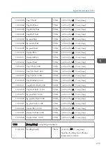


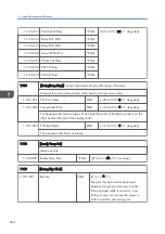


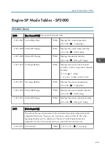


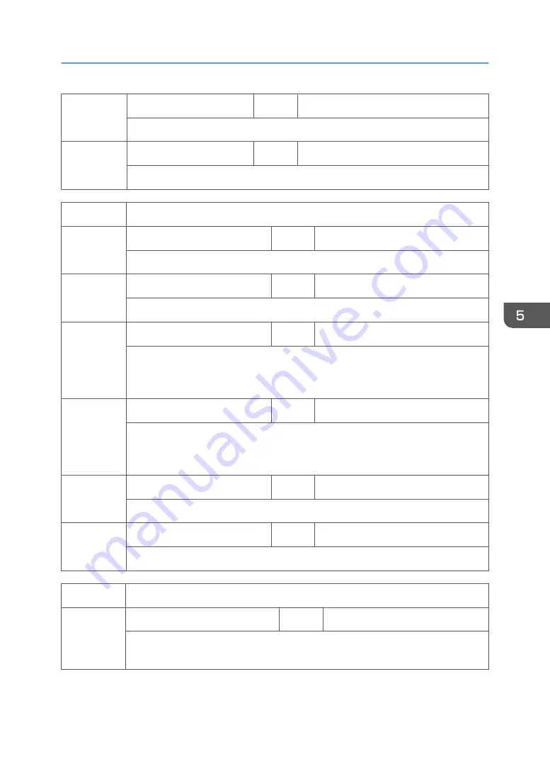
1-109-002
Pre-Idling Time
*ENG
[0 to 120 / 0 / 1 sec/step]
Specifies the fusing rotation time before executing SP1109-001.
1-109-003
Stop Time
* ENG
[5 to 30 / 20 / 1 sec/step]
Specifies the time for measuring the nip.
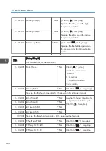
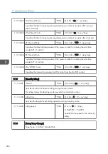
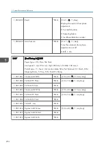
1112
[Env.Crrct:Fusing]
1-112-001 Temp.:Thresh:Low
*ENG
[10 to 23 / 17 / 1 deg/step]
Specifies the threshold temperature for low temperature condition.
1-112-002 Temp.:Thresh:High
*ENG
[24 to 40 / 30 / 1 deg/step]
Specifies the threshold temperature for high temperature condition.
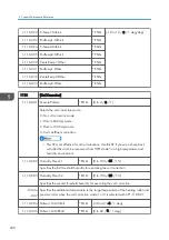
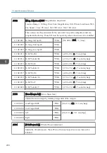
1-112-003 Low Temp Correct
*ENG
[0 to 15 / 5 / 1 deg/step]
Specifies the temperature correction for the heating roller. When the low temperature
condition (specified with SP1112-001) is detected, the value of this SP is added to the
heating roller temperature.
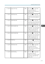
1-112-004 High Temp Correct
*ENG
[0 to 15 / 3 / 1 deg/step]
Specifies the temperature correction for the heating roller. When the high temperature
condition (specified with SP1112-002) is detected, the value of this SP is subtracted
from the heating roller temperature.
1-112-005 J-Lo Temp. Corr
*ENG
[0 to 15 / 5 / 0.1 deg/step]
Specifies the temperature correction in the paper feeding for the heating roller.
1-112-006 J-Hi Temp. Corr
*ENG
[0 to 15 / 3 / 0.1 deg/step]
Specifies the temperature correction in the paper feeding for the heating roller.
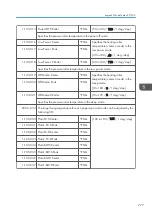
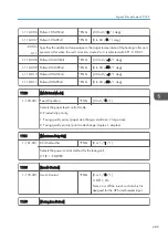
1113
[Standby Mode Set]
1-113-001 Wait Time AF Ready
*ENG
[0 to 60 / 30 / 1 sec/step]
Specifies the time for keeping the target temperature without any jobs after reloading
(SP1105-082).
Engine SP Mode Tables: SP1000
285
Summary of Contents for Z-P2
Page 1: ...Model Z P2 Machine Codes M257 Field Service Manual April 2015 ...
Page 2: ......
Page 30: ...1 Product Information 28 ...
Page 73: ...9 Install the securing holder E 10 Reassemble the machine Tray Heater 71 ...
Page 86: ...3 Preventive Maintenance 84 ...
Page 92: ...5 Left cover B Right Cover 1 Open the duplex unit A 4 Replacement and Adjustment 90 ...
Page 128: ...5 Open the upper cover A 4 Replacement and Adjustment 126 ...
Page 131: ...4 The left stay A x 4 5 Rear holder bracket A x 2 Image Transfer 129 ...
Page 139: ...3 Remove the two screws 4 ID sensor board bracket A x 1 Image Transfer 137 ...
Page 141: ...4 Exit the SP mode Image Transfer 139 ...
Page 146: ...2 Temperature Humidity sensor A x 1 x 1 4 Replacement and Adjustment 144 ...
Page 187: ...3 Bracket A x 1 4 Release the paper feed unit A x 1 Paper Feed 185 ...
Page 201: ...5 Inner left upper cover page 94 6 Paper exit unit holder A x 1 Paper Exit 199 ...
Page 211: ...6 Release the left arm A x 1 Duplex Unit 209 ...
Page 215: ...3 Duplex lower guide plate A 4 Duplex upper guide plate A x 7 Duplex Unit 213 ...
Page 220: ...8 Right and left arms A x 2 each 4 Replacement and Adjustment 218 ...
Page 221: ...9 Duplex By pass motor bracket with the frame A x 6 10 Guide plate A x 4 Duplex Unit 219 ...
Page 245: ...5 Disconnect the connector 6 Disconnect the six connectors x 1 Electrical Components 243 ...
Page 254: ...4 Replacement and Adjustment 252 ...
Page 564: ...5 System Maintenance Reference 562 ...
Page 637: ...Model Z P2 Machine Codes M257 Appendices February 2015 ...
Page 638: ......
Page 640: ...2 ...
Page 648: ...1 Appendix Specifications 10 ...
Page 652: ...MEMO 14 ...
Page 653: ...MEMO 15 ...
Page 654: ...MEMO 16 EN ...