


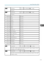


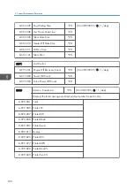

8-451-008 Tray 7
Not used
8-451-009 Tray 8
Not used
8-451-010 Tray 9
Not used
8-451-011 Tray 10
Not used
8-451-012 Tray 11
Not used
8-451-013 Tray 12
Not used
8-451-014 Tray 13
Not used
8-451-015 Tray 14
Not used
8-451-016 Tray 15
Not used
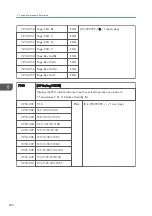
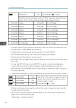
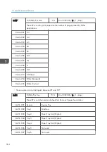
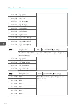
8461
T:PrtPGS/Ppr Type
*CTL
[0 to 9999999/ 0 / 1 /step]
These SPs count by paper type the number pages printed by all applications.
• These counters are not the same as the PM counter. The PM counter is based on
feed timing to accurately measure the service life of the feed rollers. However,
these counts are based on output timing.
• Blank sheets (covers, chapter covers, slip sheets) are also counted.
• During duplex printing, pages printed on both sides count as 1, and a page
printed on one side counts as 1.
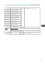
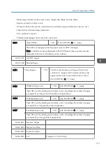
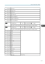
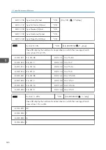
8464
P:PrtPGS/Ppr Type
*CTL
[0 to 9999999/ 0 / 1 /step]
These SPs count by paper type the number pages printed by the printer application.
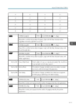
8-46x-001 Normal
8-46x-002 Recycled
8-46x-003 Special
8-46x-004 Thick
8-46x-005 Normal (Back)
8-46x-006 Thick (Back)
8-46x-007 OHP
8-46x-008 Other
Engine SP Mode Tables - SP8000
515
Summary of Contents for Z-P2
Page 1: ...Model Z P2 Machine Codes M257 Field Service Manual April 2015 ...
Page 2: ......
Page 30: ...1 Product Information 28 ...
Page 73: ...9 Install the securing holder E 10 Reassemble the machine Tray Heater 71 ...
Page 86: ...3 Preventive Maintenance 84 ...
Page 92: ...5 Left cover B Right Cover 1 Open the duplex unit A 4 Replacement and Adjustment 90 ...
Page 128: ...5 Open the upper cover A 4 Replacement and Adjustment 126 ...
Page 131: ...4 The left stay A x 4 5 Rear holder bracket A x 2 Image Transfer 129 ...
Page 139: ...3 Remove the two screws 4 ID sensor board bracket A x 1 Image Transfer 137 ...
Page 141: ...4 Exit the SP mode Image Transfer 139 ...
Page 146: ...2 Temperature Humidity sensor A x 1 x 1 4 Replacement and Adjustment 144 ...
Page 187: ...3 Bracket A x 1 4 Release the paper feed unit A x 1 Paper Feed 185 ...
Page 201: ...5 Inner left upper cover page 94 6 Paper exit unit holder A x 1 Paper Exit 199 ...
Page 211: ...6 Release the left arm A x 1 Duplex Unit 209 ...
Page 215: ...3 Duplex lower guide plate A 4 Duplex upper guide plate A x 7 Duplex Unit 213 ...
Page 220: ...8 Right and left arms A x 2 each 4 Replacement and Adjustment 218 ...
Page 221: ...9 Duplex By pass motor bracket with the frame A x 6 10 Guide plate A x 4 Duplex Unit 219 ...
Page 245: ...5 Disconnect the connector 6 Disconnect the six connectors x 1 Electrical Components 243 ...
Page 254: ...4 Replacement and Adjustment 252 ...
Page 564: ...5 System Maintenance Reference 562 ...
Page 637: ...Model Z P2 Machine Codes M257 Appendices February 2015 ...
Page 638: ......
Page 640: ...2 ...
Page 648: ...1 Appendix Specifications 10 ...
Page 652: ...MEMO 14 ...
Page 653: ...MEMO 15 ...
Page 654: ...MEMO 16 EN ...