


Service SP Mode Tables
SP1-XXX (Service Mode)
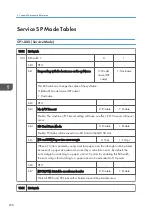
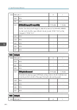
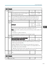
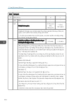
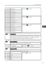
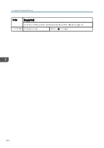
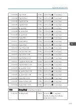
1001 Bit Switch
001 Bit Switch 1
0
1
bit 0
DFU
-
-
bit 1
Responding with the hostname as the sysName
0: Model
name (PnP
name)
1: Hostname
This Bit Switch can change the value of the sysName.
0: (default): Model name (PnP name)
1: Host name
bit 2
DFU
-
-
bit 3
No I/O Timeout
0: Disable
1: Enable
Enable: The machine I/O Timeout setting will have no effect. I/O Timeouts will never
occur.
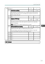
bit 4
SD Card Save Mode
0: Disable
1: Enable
Enable: Print jobs will be saved to an SD Card in the GW SD slot.
bit 5
[PS and PDF] Paper size error margin
0: ±5pt
1: ±10pt
When a PS job is printed by using a custom paper size, the job might not be printed
because of a paper size mismatch caused by a calculation error. By default, the
error margin for matching to a paper size is ±5 points. By enabling this Bit Switch,
the error margin for matching to a paper size can be extended to ±10 points.
bit 6
DFU
-
-
bit 7
[RPCS,PCL]: Printable area frame border
0: Disable
1: Enable
Prints all RPCS and PCL jobs with a border around the printable area.
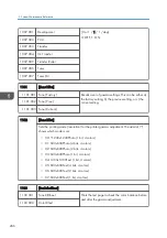
1001 Bit Switch
5. System Maintenance Reference
258
Summary of Contents for Z-P2
Page 1: ...Model Z P2 Machine Codes M257 Field Service Manual April 2015 ...
Page 2: ......
Page 30: ...1 Product Information 28 ...
Page 73: ...9 Install the securing holder E 10 Reassemble the machine Tray Heater 71 ...
Page 86: ...3 Preventive Maintenance 84 ...
Page 92: ...5 Left cover B Right Cover 1 Open the duplex unit A 4 Replacement and Adjustment 90 ...
Page 128: ...5 Open the upper cover A 4 Replacement and Adjustment 126 ...
Page 131: ...4 The left stay A x 4 5 Rear holder bracket A x 2 Image Transfer 129 ...
Page 139: ...3 Remove the two screws 4 ID sensor board bracket A x 1 Image Transfer 137 ...
Page 141: ...4 Exit the SP mode Image Transfer 139 ...
Page 146: ...2 Temperature Humidity sensor A x 1 x 1 4 Replacement and Adjustment 144 ...
Page 187: ...3 Bracket A x 1 4 Release the paper feed unit A x 1 Paper Feed 185 ...
Page 201: ...5 Inner left upper cover page 94 6 Paper exit unit holder A x 1 Paper Exit 199 ...
Page 211: ...6 Release the left arm A x 1 Duplex Unit 209 ...
Page 215: ...3 Duplex lower guide plate A 4 Duplex upper guide plate A x 7 Duplex Unit 213 ...
Page 220: ...8 Right and left arms A x 2 each 4 Replacement and Adjustment 218 ...
Page 221: ...9 Duplex By pass motor bracket with the frame A x 6 10 Guide plate A x 4 Duplex Unit 219 ...
Page 245: ...5 Disconnect the connector 6 Disconnect the six connectors x 1 Electrical Components 243 ...
Page 254: ...4 Replacement and Adjustment 252 ...
Page 564: ...5 System Maintenance Reference 562 ...
Page 637: ...Model Z P2 Machine Codes M257 Appendices February 2015 ...
Page 638: ......
Page 640: ...2 ...
Page 648: ...1 Appendix Specifications 10 ...
Page 652: ...MEMO 14 ...
Page 653: ...MEMO 15 ...
Page 654: ...MEMO 16 EN ...