3152B User Manual
Publication No. 980935 Rev. A
selected, the instrument generates the unmodulated carrier
frequency (CW) until a valid signal is applied. When the second
option is selected, the instrument generates a DC level signal until
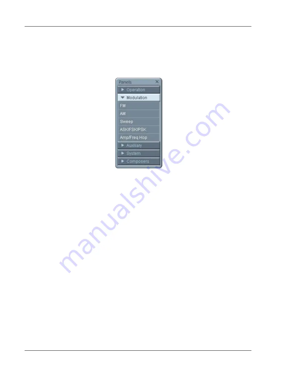
stimulated to generate a modulation cycle. The modulation options,
their associated parameters, and the various run mode options are
described separately for each of the panels below.
Figure 4-13, Modulation Panels
FM
The FM panel (Figure 4-14) contains parameters for controlling the
amplitude modulation function. To turn the FM function on and off,
click on the FM button in the State group. The various groups in the
FM panel are described below.
State
The State button turns on and off the FM function.
FM Parameters
This group contains parameters that allow complete control over the
FM function. These are:
CW Frequency
– The CW Frequency is the frequency of the pre-
modulation carrier waveform. In case the modulating waveform is
one of the built-in standard waveforms, the modulation will be
symmetrical about the CW frequency setting.
Baseline
– The Baseline parameter affects the output
characteristics in one of the interrupted run modes (i.e., triggered,
burst). In this case this parameter defines where the signal idles
between triggers. There are two options: CW and DC. The DC
option will set the idle state to a DC level, meaning that in between
triggers, the output resides on a DC level and generates modulation
when a trigger is accepted. The CW is similar except the signal
idles on the pre-trigger CW frequency setting, executes the
modulation upon receipt of a legal trigger signal and returns to
continuous CW frequency output.
4-20 ArbConnection
EADS North America Test and Services
Artisan Technology Group - Quality Instrumentation ... Guaranteed | (888) 88-SOURCE | www.artisantg.com