4-9
1
Before Using the Products
2
Preparation
3
Connection
4
Setup
5
Adjustment
6
When in T
rouble
7
Supplement
Default: [ ]
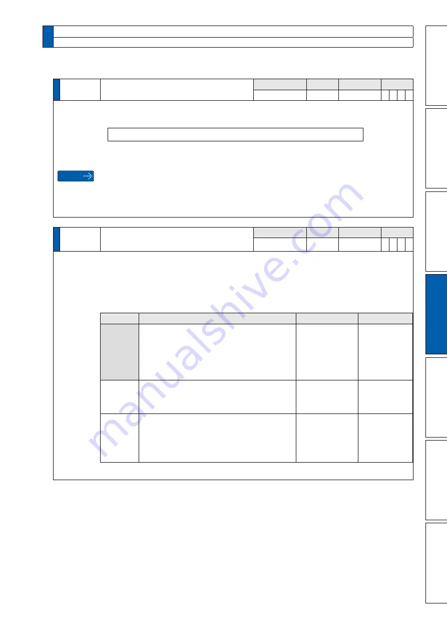
Pr0.04
Inertia ratio
Range
Unit
Default
Related
control mode
0 to 10000
%
250
*
P S T F
Caution
Set 1st inertia ratio.
You can set up the ratio of the load inertia against the rotor (of the motor) inertia.
Pr0.04 = (load inertia/ rotor inertia) × 100 [%]
The inertia ratio will be estimated at all time while the real-time auto-gain tuning is valid, and
its result will be saved to EEPROM every 30 min.
If the inertia ratio is correctly set, the setup unit of Pr1.01 and Pr1.06 becomes (Hz). When
the inertia ratio of Pr0.04 is larger than the actual, the setup unit of the velocity loop gain
becomes larger, and when the inertia ratio of Pr0.04 is smaller than the actual, the setup unit
of the velocity loop gain becomes smaller.
Pr0.05
*
Selection of command pulse input
Range
Unit
Default
Related
control mode
0 to 2
—
0
P
F
A6 according to pulse specifications,you can choose any one of the most appropriate
interface from the two interfaces.
When using open collerctor I/F,Pr0.05=2 that is recommended.
For command pulse input ,you can select either the photocoupler input or the exclusive input
for line driver as the command pulse input.
Setup value
Content
PIN NO.
Signal name
[0]
Photocoupler input
Both line driver and open collector
・
Line driver
(Permissible max frequency inputs:500 kpps)
・
Open collector
(Permissible max. input frequency:200 kpps)
No.1
No.3
No.4
No.2
No.5
No.6
OPC1
PULS1
PULS2
OPC2
SIGN1
SIGN2
1
Exclusive input for line driver
・
Line driver
(Permissible max. input frequency:8 Mpps)
No.44
No.45
No.46
No.47
PULSH1
PULSH2
SIGNH1
SIGNH2
2
Photocoupler inputs
・
Open collector
(Permissible max. input frequency:200 kpps)
No.1
No.3
No.4
No.2
No.5
No.6
OPC1
PULS1
PULS2
OPC2
SIGN1
SIGN2
Pelese refer to P.3-37 and P.3-38
.
1. Details of parameter
[Class 0] Basic setting
Buy: www.ValinOnline.com | Phone 844-385-3099 | Email: [email protected]


