5-10
OEP-3 V1 (UC)
5-4. Paper Feed and Remove Drive Unit
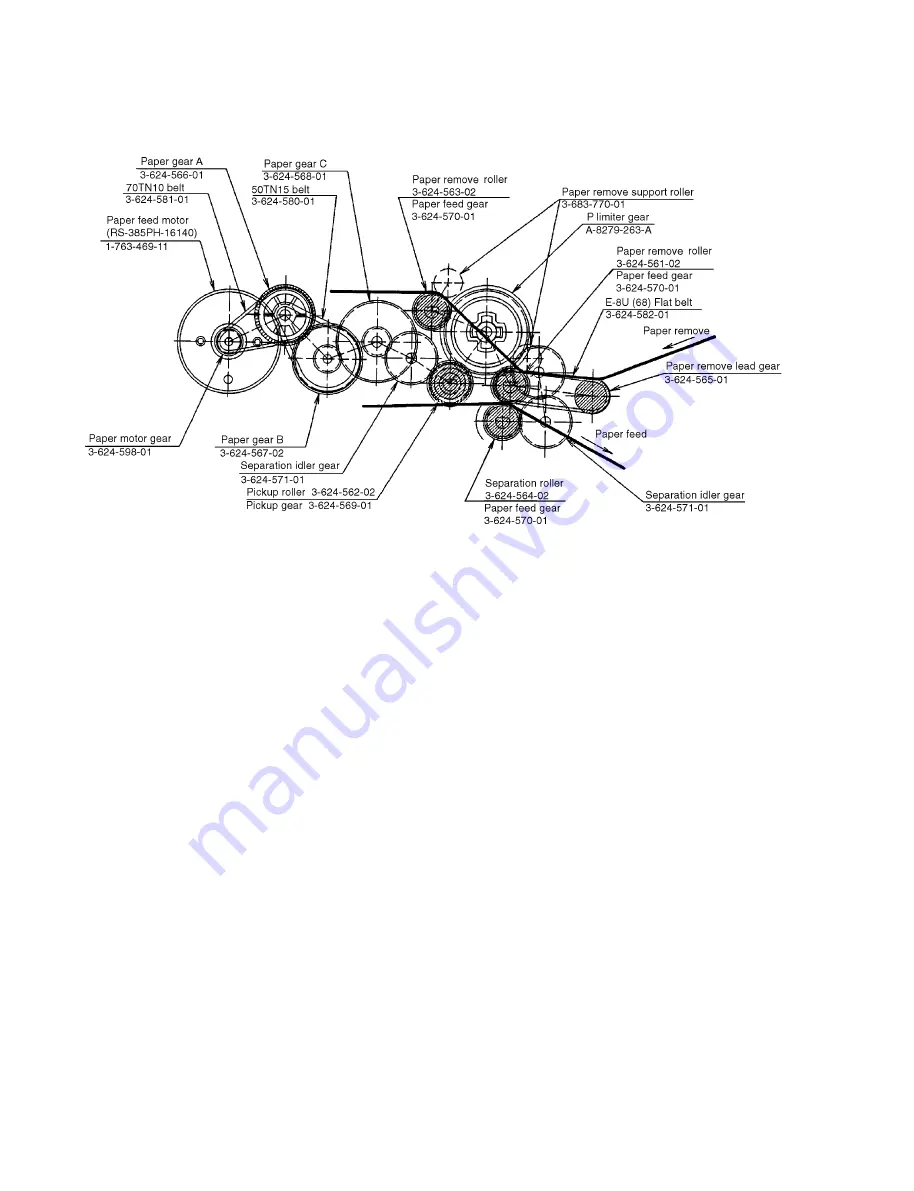
The paper feed and remove drive unit is controlled by the motion of the paper feed motor and the tray motor cam, and is
independent of the head drive unit.
The pickup roller feeds paper from out of the paper feed tray. Several sheets of paper are fed out.
When these sheets of paper are fed between the paper feed roller and the separation roller, only the top sheet of paper is
sent to the print unit by the paper feed roller. The second and latter sheets are stopped by the separation roller and left as
they are. The reason is that the rotation of the paper feed motor is transmitted to the separation roller via the P limiter gear
assembly, although it is transmitted directly to the paper feed roller. The separation roller is press-fit to the paper feed
roller only when paper is fed.
When no paper is fed or when only a single sheet of paper is fed, the driving force transmitted directly from the paper feed
roller to the separation roller becomes greater than that transmitted from the P limiter gear assembly which is a torque
limiter. Gears A and B (have the same gear size and thus cannot be distinguished on the above illustration) of the P limiter
gear assembly slip and the separation roller also turn in a forward direction. When two or more sheets of paper are put
between the paper feed roller and the separation roller, the force transmitted directly from the paper feed roller to the
separation roller weakens because of paper slippage and the driving force from the P limiter gear assembly increases.
Gears A and B of the P limiter gear assembly rotate in the same direction and the separation roller rotates in the reverse
direction.
As mentioned above, a single sheet of paper is fed through the forward rotation of the separation roller. For two or more
sheets of paper, the separation roller rotates in the reverse direction and thus only the top sheet is fed and the second and
latter sheets are returned.
Printed paper is led into the paper feed and remove unit by the paper remove lead roller, and delivered to the paper remove
unit by the paper feed roller (rear side) and paper remove roller.
Summary of Contents for OEP-3
Page 1: ...COLOR VIDEO PRINTER OEP 3 SERVICE MANUAL Volume 1 1st Edition...
Page 6: ......
Page 80: ......
Page 119: ...4 11 OEP 3 V1 UC Memory Configuration Eight Frame Memory Configuration Four Frame...
Page 154: ......
Page 165: ...5 11 OEP 3 V1 UC 5 5 Direct Chuck Mechanism...
Page 176: ...2000 9 22 OEP 3 UC E 9 955 247 11...


