1-7
OEP-3 V1 (UC)
12
Introduction
Location and Function of Parts and Controls (Continued)
5
NTSC/PAL (NTSC/PAL TV) selector (80,
81)
Set this selector according to the TV system of
the input signal. If you change this setting,
turn the printer power off, then back on again.
6
REMOTE 1 connector (special mini
jack) (82)
Used to connect the MAJ-898 Remote Control
Unit (supplied) to be used as a wired remote
control unit.
7
REMOTE 2 connector (stereo mini
jack) (82)
Used to connect the RM-91 Remote Control
Unit (provided by Sony Corporation), or the
FS-36 Foot Switch (provided by Sony
Corporation).
8
REMOTE 3 connector (D-SUB 9-pin)
(82)
Used to connect the FS-30 Foot Switch
(provided by Sony Corporation). Or input
remote control pulse signals for automatic
printing.
9
RS-232C connector (82)
Used to connect the computer to control the
printer. For details, contact your Olympus
representative or the nearest Olympus service
center.
0
-
AC IN connector
Used to connect the printer to a wall outlet
with the supplied power cord.
qa
T
OUTPUT connectors (81)
Used to connect the video monitor.
Refer to
“Important safeguards/notices for use
in the medical environments
” on page 2.
When
The NTSC system video
equipment is connected.
The PAL system video
equipment is connected.
Selector position
NTSC
PAL
Connector
S-VIDEO
VIDEO
RGB SYNC
COLOR : 200
Q1 A 4F:1
S
Q1
A
4
F
:
1
S
CO
L
O
R
:
2
0
0
Regular screen
Comparing the Printer
Windo
w Displa
y with the
Video
Monitor Display
You can operate the printer using either the printer window display or the video
monitor display. The printer window display has a narrower display range and show
only a limited number of characters. Use whichever method you prefer.
Connectable equipment
Video monitor with Y/C separated
input connector.
Video monitor with composite video
signal input connector
Video monitor with RGB/SYNC input
connectors.
13
Introduction
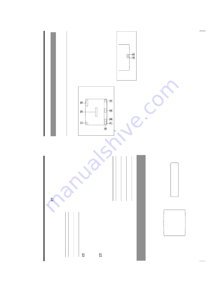
Q1 A 16: 9
S
C
Q1 A 16: 9
S
1
C (Caption) display section
C is displayed in white when the printer is set
to print a caption.
2
Message display section
Messages are displayed.
3
Ink ribbon type and remaining amount of
ink ribbon display section
Displays the ink ribbon type and the
remaining amount of ribbon (indicates the
number of printouts that can still be made
with the ribbon) when the ribbon remaining
display function is set to ON.
4
S or M (image type) display section
Indicates the type of image being displayed
on the monitor screen.
S (Source): The image from the input signal
source is displayed on the screen.
M (Memory): The image stored in memory is
displayed on the screen.
5
Printer operation mode display section
Indicates the printer application mode
(STANDARD or DUPLICATE) or type of
printouts such as multiple reduced images.
Examples:
1:
Indicates that full-size image and the
STANDARD mode are selected.
4:
Indicates that four-reduced images and the
STANDARD mode are selected
16F:
Indicates that 16-reduced images with
white borders and the STANDARD mode are
selected. When SEPARATE (image with
white borders) is set to ON on the LAYOUT
SETUP menu, F is attached.
DUP1:
Indicates that full-size image and the
DUPLICATE mode are selected.
DUP4:
Indicates that four-reduced images
and the DUPLICATE mode are selected.
a:
Indicates the type of printout
b:
Indicates the position where the cursor is currently
placed and where an image will be captured.
6
Memory page display section
Indicates the currently selected memory page.
While the image in the memory page is being
printed, the memory page indication blinks in
green. The memory page whose memory
image is queued to be printed blinks in white.
7
Q (print quantity) display
Indicates the number of copies to be printed.
This item blinks while the printer is busy.
8
Printer setting status display section
The corresponding currently selected status is
displayed when one of the LOAD USER,
LOAD COLOR, MULTI PICTURE, PRINT
QTY, INPUT SELECT, MEMORY FRM/
FLD, DISPLAY, RIBBON REMAIN or
CAPTION ON/OFF buttons is pressed.
Monitor Display
There are two types of display: a regular screen display and a menu screen
display. The two types of display are explained using the monitor display.
Regular screen display
When you first turn on the printer, the regular screen message appears.
Summary of Contents for OEP-3
Page 1: ...COLOR VIDEO PRINTER OEP 3 SERVICE MANUAL Volume 1 1st Edition...
Page 6: ......
Page 80: ......
Page 119: ...4 11 OEP 3 V1 UC Memory Configuration Eight Frame Memory Configuration Four Frame...
Page 154: ......
Page 165: ...5 11 OEP 3 V1 UC 5 5 Direct Chuck Mechanism...
Page 176: ...2000 9 22 OEP 3 UC E 9 955 247 11...


