1-43
OEP-3 V1 (UC)
84
Installation and Adjustment
Setting Up the Printer (Continued)
You can set up the printer specifications. Once you have adjusted and stored the
settings, the printer operates according to those settings until their values are
modified. You can set up the printer according to its intended purpose, connected
equipment or your individual preferences.
There are 11 menus. Functions that can be set on those menus are as follows:
Menu
COLOR ADJUST
LAYOUT SETUP
WINDOW SETUP
CAPTION
PRINTER SETUP
COLOR BALANCE
SYSTEM SETUP
USER NAME
FUNCTION SETUP
INPUT SETUP
OUTPUT SETUP
Functions to be set
Adjusting the printout color (color intensity and contrast) and
sharpness.
•
Selecting the memory mode
•
Selecting the type of printouts
•
Selecting whether white borders are added to multiple reduced
images.
•
Making a printout of mirror images
•
Selecting the lamination pattern
•
Changing the printout size
•
Changing the printout area
Entering a caption
•
Setting the print quantity
•
Selecting whether multiple reduced images are automatically stored
at regular intervals .
•
Adjusting the tone of the printout
•
Selecting the printing speed
•
Confirming whether the memory image is blurred
Adjusting the color balance
•
Adjusting the brightness of the printer window display.
•
Setting the baud rate for computer communication.
•
Selecting whether the operation and error tones sound.
•
Selecting the application mode (printer operation mode)
•
Compensating for the level of the input signal
•
Registering user settings
Editing the user name
•
Selecting the image which appears after storing the image into
memory, source image or memory image.
•
Selecting the timing of the pulse signal input to the REMOTE 2
connector
•
Selecting operation mode for automatic printing capabilities of
remote control units connected to REMOTE 2/REMOTE 3
connectors.
•
Setting the function of the CLEAR button
•
Selecting the input signal
•
Compensating for the input signals.
•
Erasing the screen display.
•
Matching the video monitor color to the printout color.
•
Selecting the output signal from the printer
•
Selecting whether the printer synchronizes with the internal sync
signal included in channel G of the RGB signals.
•
Selecting whether information on the ink ribbon is displayed
Reference page
93
39
42
54
58
121
103
103
62
28
46
99
35
53
105
117
120
119
36
88
123
123
47
113
111
69
21
85
73
90
91
82
74
Setting Up the Printer
85
Installation and Adjustment
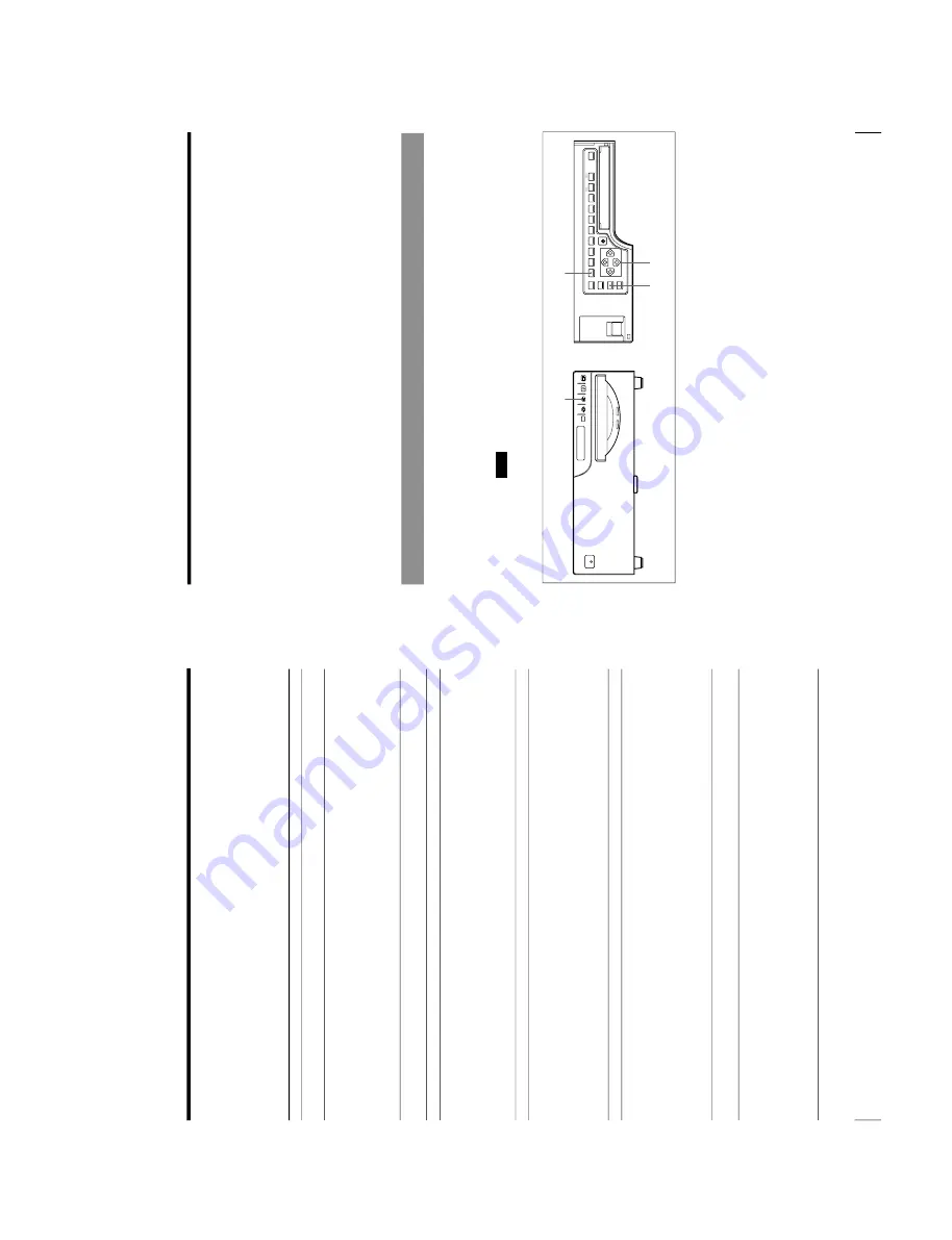
SOURCE/
MEMORY
MEMORY
PAGE
CAPTURE
ALARM
POWER
This section explains the following settings and adjustments.
•
Compensating for the input signals (on this page)
•
Matching the video monitor color to the printout color (page 90)
•
Adjusting the printout color
–
Adjusting the color intensity, contrast and sharpness (page 93)
–
Adjusting the tone of the printout (page 99)
•
Changing the printout size/printout area (page 101)
•
Adjusting the color balance (page 105)
•
Selecting the operating mode for automatic printing capability (page 111)
•
Adjusting the printer window display brightness (page 117)
•
Selecting whether to enable the operation and error tones (page 119)
•
Setting the baud rate for computer communication (page 120)
•
Selecting the lamination pattern (page 121)
•
Registering the printer settings and adjusted values as a user set (page 123)
Compensating for the Input Signals
A video image recorded under poor conditions may be of poor color quality. If the
signal is an NTSC or PAL composite video signal or separate luminance (Y) and
chrominance (C) signals, you can correct the color and level of the input signal to a
certain extent on the INPUT SETUP menu.
Note
You cannot adjust an image once it has been captured in memory. If you make
adjustments, capture that image again, after the adjustment.
1
When the memory image is displayed on the screen, press the SOURCE/
MEMORY button.
The image from the video source appears.
1
23
4
Continue to the next page
c
Summary of Contents for OEP-3
Page 1: ...COLOR VIDEO PRINTER OEP 3 SERVICE MANUAL Volume 1 1st Edition...
Page 6: ......
Page 80: ......
Page 119: ...4 11 OEP 3 V1 UC Memory Configuration Eight Frame Memory Configuration Four Frame...
Page 154: ......
Page 165: ...5 11 OEP 3 V1 UC 5 5 Direct Chuck Mechanism...
Page 176: ...2000 9 22 OEP 3 UC E 9 955 247 11...


