


Oki BV1250 Installation Guide
APPENDICES
Revision 1.0
Page 271 of 334
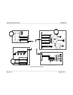
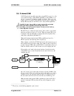
In the diagram, all of the devices in the sample network requiring IP
addresses are illustrated.
As a rule, an IP addressing scheme is created by a qualified network
administrator. In general, each IP address must be unique to the device
being addressed. In addition, the IP addresses used must be granted by, and
conform to the requirements of the governing regulatory agency; the
Internic in the United States, RIP in Europe, and APNIC in Asia and the
Pacific. In the United States the Internic requirements and the allocation of
addresses must conform to certain rules.
Overall
Subnetting
IP addressing defines subnetting. Each network location has a subnet
mask address that helps to define which digits of an IP address are
used for the network address and the host address. In this case the
sample network, the subnet address is the BV1250 default,
255.255.255.0. The subnet mask addresses for various networks may
differ from the default subnets. In the case of the Internet, the subnet
mask address will be provided by the regulating agency or the IP
address provider.
The following discussion does not attempt to address the subtleties
of IP addressing.
Units at each location have unique IP addresses. These addresses fall
within the same subnet as that of the gateway shared by the units. This
means that all IVG units connected to the same gateway will share the
network portion of their IP address with the Gateway.
In the sample network, the San Francisco, Los Angeles, and Chicago
offices are using a Class C address space (255.255.255.0), which
means that all but the final octet (0) must be the same for all devices.
The final octet for the device address cannot use the values 0 or 255.
Unit IP Addressing
In the sample network, the IP addresses have been allocated so that
each IVG has a sequential number. For example, at the New York
office, the four BV1250-E&M units are addressed in sequence so that
the last element of the Unit 1 address is .91, Unit 2 is .92, and so on.
This sequencing is for convenience only and is not a requirement of
the addressing scheme.
Finally, each location in the sample network has only a single router.
Of course, there may be more than one router at each location, and
each must be servicing its own subnet
Summary of Contents for BV1250
Page 1: ...BV1250 Internet Voice Gateway INSTALLATION GUIDE Oki Electric Industry Co Ltd...
Page 2: ......
Page 12: ...INTRODUCTION Oki BV1250 Installation Guide Page 2 of 334 Revision 1...
Page 18: ...OVERVIEW Oki BV1250 Installation Guide Page 8 of 334 Revision 1 0...
Page 20: ...PLANNING Oki BV1250 Installation Guide Page 10 of 334 Revision 1 0...
Page 142: ...FXO WORKSHEETS Oki BV1250 Installation Guide Page 132 of 334 Revision 1 0...
Page 144: ...PHYSICAL INSTALLATION Oki BV1250 Installation Guide Page 134 of 334 Revision 1 0...
Page 184: ...LOGICAL INSTALLATION Oki BV1250 Installation Guide Page 174 of 334 Revision 1 0...
Page 270: ...APPENDICES Oki BV1250 Installation Guide Page 260 of 334 Revision 1 0...
Page 329: ...Oki BV1250 Installation Guide APPENDICES Revision 1 0 Page 319 of 334...
Page 343: ...Oki BV1250 Installation Guide APPENDICES Revision 1 0 Page 333 of 334...
Page 344: ...APPENDICES Oki BV1250 Installation Guide Page 334 of 334 Revision 1 0...


