background image

Oki BV1250 Installation Guide

Revision 1.0

Page iii

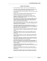
Safety Precautions


Never overload electrical outlets. Doing so can cause overheating or fire.


Never insert or drop any metallic object into openings in the equipment base
unit. Doing so will create a fire hazard or produce electrical shock.


Never handle the electrical plug with wet hands. Doing so can produce severe
electrical shock.


Never heat, pull, or place heavy objects on the power cord. Doing so can
damage the power cord and can cause fire or electric shock.


Never use a voltage other than that specified for this equipment. This
equipment is designed to operate on AC90V to 252V. Doing so can cause
electric shock, equipment failure, and fire.


Never touch the power plug terminals while the plug is connected to a power
plug outlet. Be certain that the plug is fully inserted into the plug outlet. Any
contact with the plug terminals while they are connected to the outlet can
cause fire, electric shock and other problems.


Never install this equipment in an area in which it will be exposed to lamp soot,
high humidity, or moisture. Doing so can cause premature equipment failure,
fire, electric shock and other problems.


Never install the equipment in areas with a great amount of dust, moist
environments, or areas in which other chemical reactions may create corrosive
gases which may act upon the equipment. Doing so can result in premature
equipment failure, fire, and other problems.


Never install the equipment in an area in which it will be exposed to excessive
vibration. Doing so may result in premature equipment failure, fire, and other
problems.


Never install this equipment in areas in which it will be exposed to strong
magnetic fields. Doing so may result in poor equipment performance and
possible failure.


Never install this equipment in a location in which it will be subject to falling.
Doing so can result in personal injury and equipment breakage, failure, fire,
and other hazards.


Never install this equipment in a location in which it is exposed to prolonged
direct sunlight or excessively high humidity. Doing so can cause equipment
overheating, premature failure, fire, and other problems.


Never install this equipment in an orientation other than that prescribed in this
document. This equipment has been designed for horizontal installation.
Improper orientation can cause equipment overheating, premature failure, fire,
and other problems.


Never move this equipment without first turning the power off and
disconnecting all cable connections. Doing so can result in personal injury and
damage to the equipment.


Never place heavy objects on the base unit in a manner other than that
specified in this manual. Doing so can result in personal injury or damage to
the equipment.


Never operate this equipment without a proper earth/ground connection as
described in this document. Doing so can result in electrical shock and fire.

Summary of Contents for BV1250

Page 1: ...BV1250 Internet Voice Gateway INSTALLATION GUIDE Oki Electric Industry Co Ltd...

Page 2: ......

Page 3: ...e i Safety Warning This document contains information relating to the safe installation maintenance and use of the Oki BV1250 Carefully note all safety precautions and procedures contained in this doc...

Page 4: ...without notice The contents of this document and the Maintenance Console Software have been prepared with the utmost care However if you notice an ambiguous point or omission please contact an author...

Page 5: ...pon the equipment Doing so can result in premature equipment failure fire and other problems Never install the equipment in an area in which it will be exposed to excessive vibration Doing so may resu...

Page 6: ...he quality and functionality of the Maintenance Console Software and this Installation Guide Oki Electric holds no liability for the conformity of the equipment to the purpose of use by the user and t...

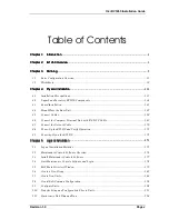
Page 7: ...3 Board Installation 141 4 4 Mount Place the Base Unit 149 4 5 Connect Cables 154 4 6 Connect the Computer Terminal Unit with RS 232C Cable 169 4 7 Connect the Network Cable 170 4 8 Power Up the BV125...

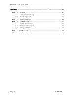
Page 8: ...y 261 Appendix B Voice Over IP Addressing 269 Appendix C Numbering Systems 273 Appendix D DNS Configuration 280 Appendix E Tone Generation 293 Appendix F Pad Control and AGC 299 Appendix G Optimizing...

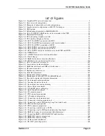
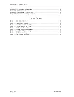
Page 9: ...n 142 Figure 4 3 E M line interface board DIP switch locations 143 Figure 4 4 RJ connector cutouts 145 Figure 4 5 Replace unit chassis cover 146 Figure 4 6 Front label placement 147 Figure 4 7 Mainten...

Page 10: ...Tables Table 3 1 Codec Default Parameters 64 Table 3 2 Codec Default Parameters 91 Table 3 3 Codec Default Parameters 125 Table 4 1 Analog Line Interface Board Kits 139 Table 4 2 FXO Line Interface Bo...

Page 11: ...network telephone numbering system should be performed by persons experienced in network administration For complex installations it may be useful to create a diagram of the network similar to those...

Page 12: ...INTRODUCTION Oki BV1250 Installation Guide Page 2 of 334 Revision 1...

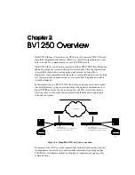
Page 13: ...rks is virtually eliminated In the simplest sense a BV1250 IVG unit converts outgoing voice or fax signals into a digital format compresses and packages the signal for transmission over digital TCP IP...

Page 14: ...accomplished by installing the desired board or boards in the base unit Line Interface Options Oki s modular design permits identical base units to be quickly and easily set up with different line in...

Page 15: ...e unit regenerates DTMF tones assuring accurate transmission when interfacing with Auto Attendant Voice Mail or Interactive Voice Response systems Voice Quality All BV1250 units provide high quality v...

Page 16: ...pliant gateways using H 323 Gatekeeper device call control address management and bandwidth control capabilities IP and Telephone Numbering Management Oki BV1250 units employ a unified telephone numbe...

Page 17: ...g Oki s Maintenance Console Software MCS running on the Windows 95 operating system For first time installation the Maintenance Console Software is used in conjunction with a common RS232C interface i...

Page 18: ...OVERVIEW Oki BV1250 Installation Guide Page 8 of 334 Revision 1 0...

Page 19: ...into existing data and telephony networks Proper planning will make the installation process go more easily and will assure that the network can be easily maintained and upgraded This chapter covers...

Page 20: ...PLANNING Oki BV1250 Installation Guide Page 10 of 334 Revision 1 0...

Page 21: ...he BV1250 s internal DNS functions A basic configuration is shown in Figure 3 1 A few conditions must be met for a BV1250 IVG installation Each BV1250 unit must be connected to the LAN using an Ethern...

Page 22: ...Revision 1 0 Hybrid configurations such as those shown in Figure 3 2 are not allowable These configurations will produce large voice delays voice quality deterioration and unreliable connections Figu...

Page 23: ...uipment E M equipped units are used to interconnect terminal equipment through one or more E M equipped PBXs E M FXO and AP FXS equipped units support up to four simultaneous voice channels Any one of...

Page 24: ...PLANNING Oki BV1250 Installation Guide Page 14 of 334 Revision 1 0 Figure 3 3 Sample network configuration with H 323 Gatekeeper...

Page 25: ...ciated with it is configured to process communications for all of the IVGs in New York PBX B communicates with units 3 and 4 only New York is also the location at which the Gatekeeper device resides T...

Page 26: ...o the IVG network Also users can dial some frequently called network numbers by using speed dial codes that have been defined during unit configuration Unit 10 on the other hand is set up to use the B...

Page 27: ...ets forth standards for multimedia communications over IP based Local Area Networks LANs and Wide Area Networks WANs and for end point terminal devices which interact across the networks When implemen...

Page 28: ...devices perform several vital functions Gatekeepers are the central points at which LAN identifiers for terminals and gateways e g telephone numbers are translated into IP and IPX addresses Gatekeeper...

Page 29: ...ice compression decompression and voice and fax data packetization and de packetization Terminals At a minimum H 323 terminals support voice communications but may also support video and data Three ot...

Page 30: ...nfiguration file takes precedence over any external DNS servers The MCS is used to generate and upload the DNS DAT file containing definitions for up to 511 units The following information is entered...

Page 31: ...methods are supported Delay dial7 Immediate start and Wink start Each unit can accommodate up to four trunk line connections PBX Analog E M Tie Lines Analog Digital Station Ports Figure 3 5 Relationsh...

Page 32: ...VG 2 Figure 3 6 Up to 30 BBV1250 E M units can be associated with a PBX As shown in Figure 3 7 Maximum PBX routing when several PBXs are interconnected through a BV1250 E M unit the maximum number of...

Page 33: ...Telephone System trunk lines In addition the AP FXS unit can be connected directly with a PBX using the Analog Loop Start Trunk board Telephone Telephone Telephone Fax Figure 3 8 IVG and analog teleph...

Page 34: ...X KEY TELEPHONE SYSTEM DIL Function Analog Station Ports IVR Analog Loop Start Trunk Board Figure 3 12 BV1250 AP FXS terminated with IVR Analog terminals connected with the BV1250 AP FXS unit should c...

Page 35: ...nd using FXO equipped units connected with a PBX The FXO to PBX connection must be analog The standard use for the FXO interface is TIA EIA 464B e g requirements for Private Branch Exchange Switching...

Page 36: ...uld only be altered based performance tests following installation In particular the FXO unit s incoming pad may need to be adjusted to accommodate the PSTN s characteristics Also an AGC Automatic Gai...

Page 37: ...orts to be configured with passwords that PSTN inbound callers use to access the Gateway They then have the option to dial a network number or of use the unit s Speed Dial feature to rapidly access fr...

Page 38: ...t is connected directly to a unit port using a 2 wire line The following information should be considered when installing and using the BV1250 s fax features Characteristics G3 fax conforms to ITU T R...

Page 39: ...e the calling party which will need to send DTMF tones by dialing numbers As a general rule it is best to avoid duplicating detection on two communicating BV1250 units This can be accomplished by alwa...

Page 40: ...atures to be implemented will need to be prepared The worksheets described in this section are designed to assist in the network planning process and should be filled out before beginning physical and...

Page 41: ...rganize information about BV1250 units in a summary fashion so that the relationship between the network IP addressing and numbering plan can be easily seen Also if DNS facilities are used instead of...

Page 42: ...nformation contained on this worksheet will be transferred to individual unit setup worksheets discussed later in this chapter See sections 5 7 2 and 5 7 3 for Maintenance Console Software procedures...

Page 43: ...255 0 206 45 11 1 Los Angeles V1 00 FXO Unit 10 206 45 11 35 255 255 255 0 206 45 11 1 Group Name Use the Group Name field to assign a group in which to create and store BV1250 units in the Maintenan...

Page 44: ...AP E M OD Units E M interface for Europe and Japan BV1250 System V1 0 OD E M Units E M interface for US BV1250 System V1 0 EM FXO Units FXO interface for US and Japan BV1250 System V1 0 FX Unit Name U...

Page 45: ...values are incompatible Although the MCS rejects conflicting addresses care must be used if the VHUB_SUBNET parameter is configured manually using BV1250 on line commands Gateway 1 IP Address GW_IP 12...

Page 46: ...ociated with each of the network units For each unit the unit s Gateway is the one that will be accessed by the unit if Gateway 1 i e the primary Gateway fails The BV1250 unit s gateway is typically a...

Page 47: ...e 2 or Type 5 OD 2W 4W T1 T2 T5 OD Unit 1 E M Rack 3 3 Unit 2 E M Rack 3 3 Unit 3 E M Rack 3 3 Unit 4 E M Rack 3 3 Unit 5 AP Desktop Unit 6 FXO Desktop Unit 7 FXO Desktop Unit 8 AP Rack Unit 9 FXO Rac...

Page 48: ...on all E M equipped BV1250 units in the network Possible configuration include Type 1 2 Wire Type 1 4 Wire Type 2 2 Wire Type 2 4 Wire This configuration is determined by the characteristics of the P...

Page 49: ...BV1250 Network Units Numbering Plan Worksheet Group Name Unit Name IVG Office Code Voice Code Fax Code Dialing Access Code First Last New York Unit 1 91 None None First New York Unit 2 92 None None Fi...

Page 50: ...server configuration files See Appendix D for a discussion of this subject Group Name Use the Group Name field to assign a group in which to create and store BV1250 units in the Maintenance Console S...

Page 51: ...r used to inform other applications of an outgoing voice call The code can be up to eight characters in length and can include the digits 0 to 9 as well as the and symbols There is no default value In...

Page 52: ...Unit Name and IP Address Terminal Destination Office Code Remaining Digits Comments Unit 1 133 149 1 91 215 3 Local station number A Unit 1 133 149 1 91 217 3 Local station number A Unit 1 133 149 1 9...

Page 53: ...nformation in conjunction with an external DNS facility can help to speed network connections See Appendix D for details regarding Network DNS configuration In the DNS DAT file an Office Code for an A...

Page 54: ...cause this unit is associated with a Trunk Group routed to PBX 27 No additional digits are included so the Destination Office Code is simply 27 If FXO units are arranged into a Trunk Group record that...

Page 55: ...folders Use the Common Configuration worksheet to record values for parameters that are common to many units within a network The common configuration items include DNS SNMP Gatekeeper and Notify E m...

Page 56: ...DNS capabilities can speed connection time for specified numbers and can also be used to configure emergency connections in the event of a server failure See Appendix D of this document The informatio...

Page 57: ...t sample leaves this field empty Access Time DNS_TIME Use the DNS Access Time field to record the DNS access time requirements This value specifies the time at which the DNS server will be accessed to...

Page 58: ...value for this field In the sample there is no Trap 2 IP address Trap IP 3 SNMP_TRPDST Record the IP address for a third Transmission facility The IP address must conform to Internet Protocol addressi...

Page 59: ...must conform to Internet Protocol addressing requirements e g nnn nnn nnn nnn where nnn a value of 0 to 255 excluding 0 0 0 0 and 255 255 255 255 There is no default value for this field In the sampl...

Page 60: ...secondary backup SNMP server is configured record the IP address of the secondary server The IP address must conform to Internet Protocol addressing requirements e g nnn nnn nnn nnn where nnn a value...

Page 61: ...tion is used to physically install and logically configure a unit Most of the logical parameters are configured using the Maintenance Console Software Once this information is entered into the softwar...

Page 62: ...Disable Port 2 2 DTMF Both No 0 12 Disable Port 3 3 DTMF Both No 0 12 Disable Port 4 4 DTMF Both No 0 12 Disable VOICE MODE Protocol H 323 Qual Effic Payload Qual Effic Bandwidth Primary CODEC G723 1...

Page 63: ...must be done before units Gateways can be created When the BV1250 s internal DNS functions and or an external DNS sever is used in the network grouped units must use the same DNS configuration This i...

Page 64: ...it s unique IP address This address must conform to Internet Protocol addressing requirements e g nnn nnn nnn nnn where nnn a value of 0 to 255 excluding 0 0 0 0 and 255 255 255 255 The unit is shippe...

Page 65: ...ss of the secondary gateway if present The BV1250 unit s second gateway address is optional It is used to designate a secondary backup device to be accessed in the event that the primary gateway becom...

Page 66: ...eely mixed The default User password is mainte In the sample the User password is entered as mainte e g the default password If a password is lost it cannot be recovered In the event of a lost passwor...

Page 67: ...er and the optional Voice and Fax Access Codes 24 Voice and Fax Access codes can be sent at the beginning or end of a dialed number sequence Access Code IVG Office Code Extension No 25 1 to 8 digits 1...

Page 68: ...an outgoing voice call The code can be up to eight characters in length and can include the digits 0 to 9 as well as the and symbols There is no default value In the sample no voice Access Code is def...

Page 69: ...is feature is optional If not used all calls terminate at the individual ports of the unit Group HNT Up to four hunt groups can be created For each group to be created record the Port No in priority o...

Page 70: ...ld indicates the port to be configured e g ports 1 to 4 To the right of each port are fields for the port s setup parameters Provide information for each of the unit s active ports Ext No TERM Use the...

Page 71: ...cating BV1250 units This can be accomplished by always selecting the DTMF detect Outgoing parameter when using DTMF regeneration PAD In and PAD Out PAD_VALUE For each port use the PAD In and PAD Out f...

Page 72: ...e effect when both are configured AGC For each port record the AGC function levels to be used if this feature is to be enabled The AGC Automatic Gain Control feature operates at the PAD In side of the...

Page 73: ...possible H 323 Default Use this protocol to have the unit use H 323 voice control protocol RTP RTCP Oki Use this protocol to have the unit use Oki s proprietary voice control protocol 28 In the sample...

Page 74: ...ficiency to Quality settings will vary based on the Codec selected In the sample G729 is the only Codec configured for use Efficiency to Quality VOICECOND The ratio of Payload to Bandwidth for each Co...

Page 75: ...can be bypassed as calls are rerouted through active links Figure 3 17 illustrates how the various parameters underlined interact in the error detection process Start Poll at Regular period OK Poll at...

Page 76: ...d during this period the Regular Timing is resumed In the sample worksheet the Error Detect Timing field is recorded as the default 3 seconds Disconnect on Errors Use the Disconnect on Errors field to...

Page 77: ...e default value 1721 This value affects the four ports The designated port and the next three ports in sequence e g 1721 1722 1723 and 1724 RTP Start Port RTP_PORT Use the RTP Start Port field to reco...

Page 78: ...and network and can be entered into the Maintenance Console Software using the Common Configuration dialog Alternatively the Unit Configuration dialog allows these facilities to be configured for ind...

Page 79: ...sation Several configuration parameters can be configured for this feature Maximum Receive Buffer Size Record the maximum allowable size of the recovery buffer In most cases the default size 1920 ms w...

Page 80: ...M law Flag Record the PCM coding and compression standard to be used by the unit A law is the PCM used in Europe and in areas outside of North America M law is the PCM voice coding and compression st...

Page 81: ...connected to its interface This defines the frequency of the ring generated The default for Ringer Frequency is 20hz e g US standard Ringer Interval Record the Ringer Interval for the AP FXS unit The...

Page 82: ...lso see the network diagrams in appendices B and C Once this worksheet is completed the information is used to physically install and logically configure a unit The logical parameters are configured u...

Page 83: ...ard Timing 2560 ms PAD in 0dB PAD out 0dB DTMF Detect Outgoing AGCdBm Disabled Port 1 1 0 0 DTMF 2560 0 0 Out Disable Port 2 1 0 0 DTMF 2560 0 0 Out Disable Port 3 1 0 0 DTMF 2560 0 0 Out Disable Port...

Page 84: ...ETUP See Common Configuration Worksheet GATEKEEPER RECOVERY DELAY Max Receive Buffer 1920 ms 1920 Start Recovery 200 ms 200 End Recovery 30 ms 30 OTHER Fan Fault Block Non Block Block Blocking a law m...

Page 85: ...must be done before units Gateways can be created When the BV1250 s internal DNS functions and or an external DNS sever is used in the network grouped units must use the same DNS configuration This i...

Page 86: ...ce Over IP network Unit IP VHUB_IP Use this field to record a unit s unique IP address This address must conform to Internet Protocol addressing requirements e g nnn nnn nnn nnn where nnn a value of 0...

Page 87: ...address of the secondary gateway if present The BV1250 unit s second gateway address is optional It is used to designate a secondary backup device to be accessed in the event that the primary gateway...

Page 88: ...entered as user e g the default password Maintenance PW PASS_M Use the Maintenance PW field to record a Maintenance access level password Passwords may be from 1 to 10 characters long and are case sen...

Page 89: ...ils Numbering Use the Numbering section of the worksheet to record the access number e g extension and Access Codes for the BV1250 being installed The information recorded is necessary to setup phone...

Page 90: ...it number is Access Code PBX Office Code Extension No 31 1 to 8 digits 1 to 8 digits 1 to 8 digits Or PBX Office Code Extension No Access Code 1 to 8 digits 1 to 8 digits 1 to 8 digits E M unit number...

Page 91: ...ols There is no default value In the sample no voice Access Code is defined Fax Access Code FAXSP The BV1250 automatically differentiates between voice and fax transmissions Use the optional Fax Acces...

Page 92: ...ports 1 to 4 To the right of each port are fields for the port s setup parameters Provide information for each of the unit s active ports Trunk Group TRK Use the Trunk Group Field to define from 1 to...

Page 93: ...eld to record the delay in milliseconds ms 33 When using Delay Timing the Wink Width parameter should be set to 0 This indicates that Wink Start is disabled See Wink Width below If the Immediate metho...

Page 94: ...s 13 448ms 14 480ms 15 512ms The default setting is 0 ms In the sample network the Wink Width parameter for all ports is not used DP DTMF TRMDLD Use the DP DTMF field to record the dialing method to b...

Page 95: ...of PAD to be introduced into the communication between a BV1250 unit and other devices PAD is a voice line gain loss function expressed in decibels dB which is introduced into communications between...

Page 96: ...r outgoing calls Incoming DTMF will be detected for incoming calls Both DTMF will be detected for incoming and outgoing calls As a general rule it is best to avoid duplicating detection on two communi...

Page 97: ...g A pattern for each Trunk Group that has been defined for the unit The relationship between ports Trunk Groups Hunt Patterns and PBX Office Codes is Per Unit Minimum Maximum Ports 1 4 Trunk Groups 1...

Page 98: ...the PBX Office Code to be accessed when calling through the BV1250 unit 8 digits maximum Every Hunt Pattern must be associated with a PBX Office Code See the E M Unit Setup Worksheet Extension EM A H...

Page 99: ...he Hunt Pattern section of the worksheet See previous Topic Up to 4 Hunt Patterns can be defined for each unit Pattern TGNPRIORITY Records lines are provided for up to four Patterns Record the Trunk G...

Page 100: ...le H 323 Default Use this protocol to have the unit use H 323 voice control protocol RTP RTCP Oki Use this protocol to have the unit use Oki s proprietary voice control protocol 38 In the sample the P...

Page 101: ...iciency to Quality settings will vary based on the Codec selected In the sample G729 is the only Codec configured for use Efficiency to Quality VOICECOND The ratio of Payload to Bandwidth for each Cod...

Page 102: ...ters underlined interact in the error detection process Start Poll at Regular period OK Poll at Error Detect period Set count 0 Check Counter and Results Disable BS1200 Error detected Counter Disconne...

Page 103: ...ld is recorded as the default 3 seconds Disconnect on Errors Use the Disconnect on Errors field to record the number of errors that will be detected before an error condition is detected Once this num...

Page 104: ...ult value 1721 This value affects the four ports The designated port and the next three ports in sequence e g 1721 1722 1723 and 1724 RTP Start Port RTP_PORT Use the RTP Start Port field to record the...

Page 105: ...and network and can be entered into the Maintenance Console Software using the Common Configuration dialog Alternatively the Unit Configuration dialog allows these facilities to be configured for indi...

Page 106: ...ation Several configuration parameters can be configured for this feature Maximum Receive Buffer Size Record the maximum allowable size of the recovery buffer In most cases the default size 1920 ms wi...

Page 107: ...in process continue and are not interrupted If a fan fault occurs setting the Fan Fault feature to Non Blocking causes the fault is disregarded and the gateway continues to function normally The defa...

Page 108: ...n the Sample Network Diagram illustrated in Figure 3 3 Also see network diagrams in appendices B and C Once this worksheet is completed the information is used to physically install and logically conf...

Page 109: ...iming 500ms Delay Timing 3584ms Guard Timing 2560ms PADin 0dB PADout 0dB DTMF Detect Outgoing AGCdBm Disabled Port 1 DISA 1 2 DTMF 500 3584 2560 0 0 No Disable Port 2 DISA 1 2 DTMF 500 3584 2560 0 0 N...

Page 110: ...Effic Bandwidth Primary CODEC G723 1 Secondary CODEC Port 1 H 323 1 6 0 7 5 G723 1 none Port 2 H 323 1 6 0 7 5 G723 1 none Port 3 H 323 1 6 0 7 5 G723 1 none Port 4 H 323 1 6 0 7 5 G723 1 none NETWOR...

Page 111: ...250 V1 0 FXO FXO A DISA details PASSWORDS 1to4digits Port 1 Comment Port 2 Comment Port 3 Comment Port 4 Comment 1 2 3 4 5 6 7 8 9 10 FXO B DIL details DIL Day Number Comment Night Number Comment Port...

Page 112: ...g Number Patterns FORWARDING Pattern 8 max Daytime Start Daytime End Pattern1 Weekdays Pattern 2 Saturdays Pattern 3 Sundays Custom Patterns Month Day Pattern 4 Pattern 5 Pattern 6 Pattern 7 Pattern 8...

Page 113: ...ust be done before units Gateways can be created When the BV1250 s internal DNS functions and or an external DNS sever is used in the network grouped units must use the same DNS configuration This inf...

Page 114: ...ld to record a unit s unique IP address This address must conform to Internet Protocol addressing requirements e g nnn nnn nnn nnn where nnn a value of 0 to 255 excluding 0 0 0 0 and 255 255 255 255 T...

Page 115: ...worksheet the Gateway 1 IP address is recorded as 206 184 223 1 Gateway 2 IP GW_IP 40 Use the Gateway address field to record the address of the secondary gateway if present The BV1250 unit s second g...

Page 116: ...ed The default User password is user In the sample the User password is entered as user e g the default password Maintenance PW PASS_M Use the Maintenance PW field to record a Maintenance access level...

Page 117: ...numbers for a BV1250 network The numbers configured in this manner may be setup to emulate familiar PSTN numbering plans and or conform to existing PBX numbering systems Behind the scenes the numberin...

Page 118: ...red into the Maintenance Console Software using the Numbering and Hunt Pattern folders In addition if internal and or external DNS functions are used in the network this information is used in the DNS...

Page 119: ...fferentiates between voice and fax transmissions Use the optional Fax Access Code field to record a number used to inform other applications of an outgoing voice call The code can be up to eight chara...

Page 120: ...hese passwords used by callers from the PSTN or PBX side restrict unauthorized access to the network When a correct password is keyed the user is able to dial network numbers or use Speed Dial codes t...

Page 121: ...oup 2 Trunk Group 3 and Trunk Group 4 Defining Trunk Groups for FXO units is used to connect FXO units to the analog ports of PBX units and to group units into Hunt Groups for accessing a PSTN This la...

Page 122: ...sole Software the permissible settings are displayed in the DP Rate list box These values are 10 PPS 32 default 40 48 and 56 20 PPS 33 default 42 50 and 58 In the sample DP is not selected Reverse Tim...

Page 123: ...a call This is required because the PSTN must reset its line access in a specified time and if another caller attempts to use this trunk prior to the completion of the reset period a cross connect con...

Page 124: ...14dB 12dB 10dB 8dB 6dB 4dB 2dB 0dB 2dB 4dB 6dB 8dB 10dB 12dB 14dB 40dB The recommended value for a BV1250 E M E M OD unit is 0dB since the PBX introduces its own padding towards its extensions The re...

Page 125: ...calls Incoming DTMF will be detected for incoming calls Both DTM will be detected for incoming and outgoing calls As a general rule it is best to avoid duplicating detection on two communicating BV12...

Page 126: ...topic From 1 to 4 Hunt Patterns can be defined e g A pattern for each Trunk Group that has been defined for the unit The relationship between ports Trunk Groups Hunt Patterns and PBX or Hunt Group Off...

Page 127: ...n Number field to record the PBX Office Code to be accessed when calling through the PBX to which the FXO unit is connected or to record the Hunt Group Office Code for FXO units arranged into a Hunt G...

Page 128: ...ther units If a connection cannot be established in the Priority 1 group additional Trunk Groups are searched in priority order The Destination numbers searched using this feature are determined by th...

Page 129: ...tern 3 Sunday 00 00 to 24 00 The Daytime forwarding number is the only one that will be applied on Sunday Patterns 4 8 User defined patterns using a specified calendar day and time of day A Nighttime...

Page 130: ...Call Restriction feature of the FXO unit allows the restriction of dialing prefixes from 1 to 4 digits in length When a call restriction code is configured in the FXO unit dialed numbers beginning wi...

Page 131: ...he worksheet extension FX A Speed Dial numbers are associated with a two digit Speed Dial code 01 through 20 Callers from the PSTN to the FXO unit must first enter a DISA password Once the correct pas...

Page 132: ...to the PSTN and from the PSTN to the FXO unit When a handset is taken off hook to place a call through and FXO unit and no PSTN dial tone no digits will be sent on the line Record the following value...

Page 133: ...g back tone to the call origination point If the call setup process in interrupted before a connection is made the FXO unit detects that the PSTN has stopped sending the ring tone allowing the unit to...

Page 134: ...ble H 323 Default Use this protocol to have the unit use H 323 voice control protocol RTP RTCP Oki Use this protocol to have the unit use Oki s proprietary voice control protocol 47 In the sample the...

Page 135: ...iciency to Quality settings will vary based on the Codec selected In the sample G729 is the only Codec configured for use Efficiency to Quality VOICECOND The ratio of Payload to Bandwidth for each Cod...

Page 136: ...illustrates how the various parameters underlined interact in the error detection process Start Poll at Regular period OK Poll at Error Detect period Set count 0 Check Counter and Results Disable BS1...

Page 137: ...e Error Detect Timing field is recorded as the default 3 seconds Disconnect on Errors Use the Disconnect on Errors field to record the number of errors that will be detected before an error condition...

Page 138: ...ault value 1721 This value affects the four ports The designated port and the next three ports in sequence e g 1721 1722 1723 and 1724 RTP Start Port RTP_PORT Use the RTP Start Port field to record th...

Page 139: ...and network and can be entered into the Maintenance Console Software using the Common Configuration dialog Alternatively the Unit Configuration dialog allows these facilities to be configured for indi...

Page 140: ...ation Several configuration parameters can be configured for this feature Maximum Receive Buffer Size Record the maximum allowable size of the recovery buffer In most cases the default size 1920 ms wi...

Page 141: ...rocess continue and are not interrupted If a fan fault occurs setting the Fan Fault feature to Non Blocking causes the fault is disregarded and the gateway continues to function normally The default s...

Page 142: ...FXO WORKSHEETS Oki BV1250 Installation Guide Page 132 of 334 Revision 1 0...

Page 143: ...is recommended that all planning worksheets be completed The following sequenced steps make for a quick and efficient installation With experience installers may adopt variations on these procedures t...

Page 144: ...PHYSICAL INSTALLATION Oki BV1250 Installation Guide Page 134 of 334 Revision 1 0...

Page 145: ...lation The potential at signal ground SG terminal must be the same as the potential of the SG terminal of the PBX that connects the E M E M OD trunk line It is best to connect the earth at the same gr...

Page 146: ...units The following table indicates the specifications for the various cables Cable type Cores AWG 48 Dia Remarks Printed intra office cable 2 wire 24AWG 0 5 AP FXS unit Printed intra office cable 4 w...

Page 147: ...All boards in the BV1250 should be regarded as being sensitive to electrostatic discharge Suitable grounding devices should be on hand and used whenever components are handled Tools Screwdrivers diago...

Page 148: ...ocess All BV1250 boards should be treated as though they are sensitive to electrostatic discharge Avoid touching electronic board components and always use ESD protective devices when handling these b...

Page 149: ...Type Kit Contents Connector Type Pinouts BS1200 AP Interface Board Cable connectors Screws Labeling materials Packing List 1 Tip 2 Ring BV1250 FXS Interface Board Screws Labeling materials Packing Li...

Page 150: ...SG E M OD Kit The E M OD Kit provides a Type5 interface for applications in Europe and Japan This allows PBX and Key telephone system trunk lines to be directly connected to the BV1250 In general the...

Page 151: ...an E M type it may also be necessary to configure board DIP switches To remove Base Unit chassis cover 1 Remove six screws securing Base Unit chassis cover 2 Push the hook that is located on the back...

Page 152: ...ove main board Figure 4 2 Line interface board installation For E M line interface boards only configure DIP switches if necessary before installing the board in the unit chassis See Section 4 3 2 for...

Page 153: ...tered The appropriate settings for the board being installed should be designated on the Unit Setup Worksheet discussed in section 3 2 3 of this document To reconfigure E M board DIP switches 1 Locate...

Page 154: ...settings Port Switch Label 2 Wire left position 4 Wire Preset right position Port 1 SW01 2W 4W Port 2 SW11 2W 4W Port 3 SW21 2W 4W Port 4 SW31 2W 4W Table 4 6 Type1 Type 2 settings Port Switch Label...

Page 155: ...ther than DDK type In the case of BV1250 units with RJ style connectors the front panel must be prepared by removing the cutout panels as shown in Figure 4 4 To prepare the BV1250 front panel for RJ s...

Page 156: ...tall the unit cover To reinstall the cover 1 Align the top cover over the bottom case so that the cover is offset to the rear of the unit Figure 4 5 Replace unit chassis cover 2 Lower the cover onto t...

Page 157: ...ntenance activities easier Front Panel Label A BV1250 front panel label is included with the line interface board installed Pink for AP FXS type board Purple for E M type board and Green for FXO type...

Page 158: ...bel with proper location at the rear of the unit as shown in Figure 4 7 4 Stick the label into place and press to assure complete contact with mounting surface 5 In the case of a base unit containing...

Page 159: ...physical damage Figure 4 9 illustrates recommended minimum clearances Figure 4 9 Base unit footprint and clearance dimensions Keep the following considerations in mind when locating the base unit Orie...

Page 160: ...base unit Unevenly distributed loads may cause chassis damage below the 20lb limit To place the unit at a desktop location 1 Orient the unit and position it on a suitable surface providing adequate c...

Page 161: ...rance for maintenance purposes If the rack has a rear cover this cover should be equipped with ample provisions for ventilation Ventilation may be either passive holes or active fan The vertical posit...

Page 162: ...base unit 2 Attach the mounting brackets to the sides of the base unit using four of the supplied screws 4 metric or 4 unified fine thread Figure 4 10 Rack mount bracket installation Swap the mounting...

Page 163: ...the Base Unit into the rack using the supplied four 5 mm screws Use the stopping screw supplied with rack mounting kit to support the base unit during final alignment and attachment Figure 4 11 Securi...

Page 164: ...r Cable Ground Cables Interface Cables RS 232C Cable LAN Cable With the exception of the power cable all cables must be prepared during the installation process In addition cable restraints should be...

Page 165: ...nit To install the power cable 1 Turn the BV1250 power switch to the OFF position 2 Plug the 3 pole female connector on the supplied power cable into the male power connector located at the rear of th...

Page 166: ...should be taken into consideration when preparing grounding wires Determine the proper length and prepare Frame Ground cable and Signal Ground cable For all cables use IV insulated vinyl wire that is...

Page 167: ...the base unit and to the left of the power connector to secure one end of the FG and SG grounding cables 2 Connect the other end of the frame grounding cable to a protective earth grounding point 3 C...

Page 168: ...each connector split cable and separate end of the 2 wire printed office cable into two cores 2 Insert cores into RJ11 connector in accordance with the following diagram Figure 4 17 FXS connector prep...

Page 169: ...face cables below To connect the analog interface cables 1 Select a port for the connection and verify that the port number will be used for a telephone extension 2 Connect the prepared cable connecto...

Page 170: ...TS or PBX Analog Loop Start Trunk Board Terminal Block DDK RJ11 Figure 4 21 Connecting a unit to PBX analog Loop Start trunk board To complete the installation all interface cables should be secured t...

Page 171: ...re the wires in the RJ connector Repeat these steps for each port to be used maximum of 4 Repeat these steps for each port to be used maximum of 4 then proceed to the procedure below To connect the FX...

Page 172: ...d verify that the port number will be used for a telephone extension 2 Connect the prepared cable connector to a TEL connector 1 through 4 located at the front of the BV1250 3 Connect the other connec...

Page 173: ...M board 2 Peel the backing from labels and affix to connectors that have been matched with ports on the BV1250 front panel Figure 4 26 E M unit connector orientation and label placement 3 For each co...

Page 174: ...has not been released at the time of release When available cabling instructions for this model will be provided During installation connectors are aligned upside down so that the connections are mad...

Page 175: ...VG SG Ground for E From IVG to PBX To connect the interface cables to the BV1250 E M 1 Match the connection port with the labeled connector ends nA and nB verifying that the correct port number is sel...

Page 176: ...0 E M OD unit 1 For each connector split cable and separate the cable into 6 individual cores 2 With shielding in place insert separated cores into connector using caution to visually confirm that the...

Page 177: ...o avoid reversing the specified order Figure 4 29 E M OD connector wiring To connect the interface cables to the BV1250 E M OD 1 Verify the port numbers to be interconnected with the PBX trunk lines 2...

Page 178: ...nd wire tie packaged with the BV1250 base unit and the cable support bracket installed at the right side of the base unit On desktop units the bracket is attached to the unit chassis On rack mounted u...

Page 179: ...The pin configuration for the serial cable is shown in Figure 4 31 Figure 4 31 RS 232C pin configuration To connect the computer with the BV1250 unit 1 Turn the computer power OFF 2 Connect the RS 23...

Page 180: ...ation 2 Connect the other end of the 10BaseT cable to the remote LAN equipment e g router Ethernet switch or hub When connecting the BV1250 directly to a router use a 10BaseT Cross Rollover cable Use...

Page 181: ...the following during the POWER ON process When the power switch is toggled to the ON position check for the following indications Power Online Alarm and Busy lamps light up during the initialization p...

Page 182: ...0 4 9 Powering Down the BV1250 It is sometimes necessary to turn the BV1250 unit OFF This is the case for instance during some forms of maintenance or when relocating the unit To turn the BV1250 power...

Page 183: ...tallation process described in this chapter involves the following operations Initialize the unit with new IP addressing information Configure unit specific parameters Upload configuration files and r...

Page 184: ...LOGICAL INSTALLATION Oki BV1250 Installation Guide Page 174 of 334 Revision 1 0...

Page 185: ...e done locally or remotely Configure OFDD VHO and DNS DAT files off line and use an FTP link to upload the configuration files to a unit Configure a unit directly over a serial connection line by line...

Page 186: ...permit communication with the unit over the LAN an Ethernet Network card using an RJ45 connector is also required The Maintenance Console Software user s interface conforms to Windows 95 conventions a...

Page 187: ...ted at the lower left hand side of the Windows desktop and select the Run command 4 In the Run dialog box type D Setup where D represents is the letter of the CD drive and click on the OK button 5 Fol...

Page 188: ...he MCS should be removed from the computer prior to running MCS Version 5 0 3 The MCS startup screen displays for a few seconds and is then followed by the Startup Password dialog box After a few seco...

Page 189: ...bar and contains the program menus Unit Edit Tools View and Help To view the contents of a menu place the mouse cursor over the menu item and click the left mouse button then select the desired item...

Page 190: ...the left mouse button over a Group or Main icon Units Pane The Units pane is used to create and display units IVG Gateways and Gatekeepers within groups and to edit unit data A new Gateway or Gatekee...

Page 191: ...of 334 Status Line The status line is displayed beneath the Directory Window It shows summary information about the current status of the Maintenance Console Software display This bar can be removed a...

Page 192: ...e they will be in the same location Groups can be created all at once or one at a time as the network setup process proceeds Use the information recorded in the Network and Unit Configuration workshee...

Page 193: ...d and type a new group name Also type comments into the Comment field if desired 3 Click on the OK button to accept the information displayed in the fields or Cancel to abort the changes The MCS updat...

Page 194: ...er to first reconfigure the unit s IP addressing information to match that of the existing LAN using a direct RS 232C serial cable connection The Maintenance Console Software s Unit Information Setup...

Page 195: ...a serial communications port other than Com 1 is being used on the computer terminal used for unit initialization the MCS Options item must be selected from the Tools menu to reconfigure the Com port...

Page 196: ...the Unit menu The worksheet for this task is discussed in section 3 2 2 of this document Hints Click the Toolbar Create Gateway icon Click the right mouse button in the Groups window pane and use the...

Page 197: ...d during unit configuration 1 Select the Name field and type a name for the unit 2 Use the pull down lists to configure the three Equipment parameters Unit Version and Interface The available options...

Page 198: ...Address field and enter the IP Address for the unit 2 Select the Subnet Mask field and enter the Subnet Mask IP address 3 Select the Gateway Address 1 field and enter the address of the primary Gatew...

Page 199: ...ance password is to be changed select the Password field and type the new password To enhance security an asterisk symbol will be echoed in place of each character typed If a password is lost it canno...

Page 200: ...of 334 Revision 1 0 If the password is changed and the Password and Confirm Password values are not identical the MCS will issue an error message and redisplay screen 3 so that the password fields ca...

Page 201: ...s to be changed select the Password field and type the new password To enhance security an asterisk symbol will be echoed in place of each character typed If a password is lost it cannot be recovered...

Page 202: ...of 334 Revision 1 0 If the password is changed and the Password and Confirm Password values are not identical the MCS will issue an error message and redisplay screen 3 so that the password fields ca...

Page 203: ...ion entered in the Wizard must be written directly to the unit if the unit is to be accessed using a remote e g LAN connection During subsequent remote e g LAN sessions the Unit Information Setup Wiza...

Page 204: ...tton to select the upload method As discussed in the previous note the LAN upload method should only be selected for units that have been previously initialized and are already on line in the network...

Page 205: ...only be used to configure an Oki Gatekeeper device To configure other Gatekeeper devices refer to the manufacturer s documentation To create a Gatekeeper device select the Group in which the device i...

Page 206: ...and Notify E mail These parameters can also be configured for individual units using the Unit Configuration folders described later in this chapter This may be better when adding only a few units to...

Page 207: ...ach folder as described in section 5 7 3 of this document All parameters configured in this manner will be applied to all units in the selected group or to the units selected in the Units Pane The new...

Page 208: ...MCS each unit s configuration file can be saved to a hard disk and or uploaded to unit s using the network interface 58 In the procedures discussed in this chapter the completed configuration files w...

Page 209: ...the unit In this case select the Download File from Unit radio button Once a method has been selected click on the OK button to proceed Assuming that the Saved File option is selected the MCS then di...

Page 210: ...configured In the example above the tabs reflect the fact that Unit 5 is a BV1250 unit configured with an AP FXS line interface board In most cases the order in which folders are selected for data en...

Page 211: ...corded during the unit configuration process is critical to the proper operation of the equipment and care must be taken to avoid errors Edit Data configuration tabs displayed by the MCS differ based...

Page 212: ...d for this tab Use the Unit section to view and edit unit IP addressing information Unit Displays the unit s name This field cannot be edited from this folder To change a unit s name exit the Edit Dat...

Page 213: ...recovered In the event of a lost password contact Oki Network Technologies customer support North America or your local Oki partner To change a password 1 Type the current password into the Current P...

Page 214: ...changed Subnet Mask Type a Subnet Mask IP address If the unit was setup on the terminal currently in use this value should not need to be changed Gateway Address 1 Type an IP address for the primary...

Page 215: ...ure is for configuring the unit with a predefined tone set See Appendix E for additional discussion of custom tone configuration Use the Tone field to select a predefined Tone set In the Information s...

Page 216: ...dit the unit s Office Code Office Code Type the unit s 1 to 8 digit Office Code This value is required Use the Access Code section to view and edit the unit s Voice and Fax codes and the Access Code d...

Page 217: ...sociated with the port priority configuration to the immediate left Priority port Displays the port access priority for the associated group e g when an incoming call encounters a busy port it is auto...

Page 218: ...priority port to associate with the selected Terminal Group Only those ports that are available for association are displayed In the sample above all of the available ports have already been associat...

Page 219: ...8 digit extension number to be associated with the port DP DTMF Use the pull down list to select the dialing method to be used DTMF Tone or DP Pulse Restriction This value is not set in the current v...

Page 220: ...by observation that adjustments are required AGC To enable the unit s Automatic Gain Control check the AGC check box and set the AGC sensitivity using scroll box to change the AGC dBm value It is rec...

Page 221: ...same configuration As discussed latter the Hunt Pattern folder can be used to specify a priority order in which these groups are accessed The Trunk Data fields for FXO units differ slightly from those...

Page 222: ...Timing59 Use the pull down list to select the Delay Timing in milliseconds required by the PBX to which the trunk is connected If the Immediate method is used to connect with the PBX set the Timing De...

Page 223: ...hat adjustments are required DTMF detect Use the pull down list to select the DTMF detection method to be used by the unit No ne Incoming Outgoing or Both It is recommended that this be set to Outgoin...

Page 224: ...y all ports used to form a Trunk Group will share the same configuration The Trunk Data fields for FXO units differ slightly from those for an E M Unit The E M Trunk Data folder is described in the pr...

Page 225: ...ull down list to select the Line Type feature for each active port Possible Line Types are DISA and DIL 61 To configure Line Type parameters click on the Details button DISA Details See Extension Work...

Page 226: ...of Trunk Group 1 Delete Digits Type the number of digits to be deleted from the dialed number when calling this Trunk The maximum number of Delete Digits is 32 It is important to remember that when FX...

Page 227: ...following the completion of a call in order to permit the PSTN to reset the line PAD In Use the pull down list to select the PAD value in dB to be applied to voice signals coming into the unit It is u...

Page 228: ...bove for each active port on the unit If a port on the unit is inactive select the port in the Port parameters list and click on the Clear button to logically disable the port If this is not done call...

Page 229: ...ore than one Hunt Pattern is defined then the Trunk Priority features of the BV1250 are used to configure the priority order in which alternate Trunk Groups are searched in the event that a connection...

Page 230: ...0 unit 8 digits maximum per code FXO Type the PBX or FXO Hunt Group Office Code s for FXO units arranged into a Hunt Group 8 digits maximum per code Hunt Pattern No Use the pull down list to select th...

Page 231: ...n priority order until a connection is made Up to 4 Hunt Patterns can be defined for each unit Trunk Priorities are defined for the unit as a whole The Hunt Pattern list provides records for each Hunt...

Page 232: ...fter which the BV1250 unit will automatically disconnect There only a single field in this folder Time Type the maximum call duration in minutes after which the call will be automatically disconnected...

Page 233: ...In line DIL is specified for an FXO unit s port Type a Daytime and a Nighttime number for automatic call forwarding are configured for each port Use this folder to configure the time at which the Dayt...

Page 234: ...attern to 00 00 to 24 00 Daytime only Daily Patterns For patterns 4 through 8 only configure the month and day on which the time pattern will be applied in the Daily patterns section of the folder 1 T...

Page 235: ...dated when the code is typed into the Restriction code field and the Update button is selected Restriction code Type a 1 to 4 digit code representing numbers that when dialed at the beginning of a cal...

Page 236: ...first enter a DISA password Once the correct password is entered the caller can dial the asterisk key followed the two digit Speed Dial code to access Speed Dial numbers See Extension Worksheet FX E...

Page 237: ...ction parameters may require different values to assure proper operation It is recommended that the default parameters be used unless it is determined that they must be modified in order to optimize t...

Page 238: ...BT Busy Tone time in seconds after which the unit s attempt to connect will be abandoned If 0 is indicated the feature is disabled and there will be no disconnection Auto Drop Time Type the time that...

Page 239: ...tion list and then modify the protocol field below the list using the Select protocol field The Packet parameters are modified using the Efficiency slide bar on the right side of the dialog box The Co...

Page 240: ...e control handle to the left or right to adjust the ratio The values in the read only Packet parameter fields are updated as the slide bar is manipulated CODEC Information Use the Up arrow and Down ar...

Page 241: ...time period Type the timing cycle over which the error checking packets will be transmitted during normal operation The seconds value can also be scrolled up and down with the scrolling arrows locate...

Page 242: ...the link is failed The Times value can also be scrolled up and down with the scrolling arrows located to the right of the field Reconnect after errors Type the number of times that a recovered link is...

Page 243: ...ict If a conflict is detected refer to the H 323 protocol specifications before making adjustments Use the Information section fields to modify the H 245 call start and signaling parameters RTP start...

Page 244: ...ling arrows located to the right of the field Connect time to establish Type the time seconds that will be allowed for call signaling to be established The range of acceptable values include from 1 to...

Page 245: ...tenance Console Software When an H 323 Gatekeeper is not used in the BV1250 network the BV1250 s internal DNS server and or an external DNS server are used to perform IP address to telephone number tr...

Page 246: ...s must conform to Internet Protocol addressing requirements Access Time Type the time of day 24 hour format at which the DNS server will be accessed to update the BV1250 unit s internally cached call...

Page 247: ...number translation records This value should equal the number of digits making up the shortest IVG Office Code in the network The default value for this field is 2 The digits value can also be scroll...

Page 248: ...ce Console Software Use the Parameters section to configure the Trap IP address and the Community name IP Address for Trap Transmission 1 Type the IP address for the first Trap Transmission facility T...

Page 249: ...ork Provisions are also made for a secondary backup device in the Gatekeeper Zone If no Gatekeeper is used the BV1250 s internal DNS features and or an external DNS server must be used In this case no...

Page 250: ...ction to configure the Recovery delay settings for the unit Maximum Receive Buffer Size Type or scroll to the maximum allowable size of the recovery buffer In most cases the default size 1920 ms will...

Page 251: ...cility in the Maintenance Console Software Use the Information section to enter up to two SMTP server IP addresses and up to two E mail address to which event notifications will be sent Primary SNMP S...

Page 252: ...ditions under which a fan fault notification will be generated Use the A law m law flag to configure the PCM coding and compression standard to be used by the unit Cause of Fan Fault Blocking Non bloc...

Page 253: ...aves the configuration information on disk in the unit s OFDD VHO file and returns to the MCS directory window The updated OFDD VHO file is now ready for upload to the unit using the Maintenance Conso...

Page 254: ...ne and click the Copy button on the Toolbar Click the mouse in a vacant area of the Units window pane to deselect the copied unit Then click the Paste button on the Tools bar The MCS names the copy Co...

Page 255: ...ss is critical to the proper operation of the equipment and care must be taken to avoid errors As discussed earlier when a unit is selected and the Edit Data command is used the Maintenance Console So...

Page 256: ...red for this tab Use the Unit section to view and edit unit IP addressing information Unit Displays the unit s name This field cannot be edited from this folder To change a unit s name exit the Edit D...

Page 257: ...sword contact Oki Network Technologies customer support North America or your local Oki partner To change a password 1 Type the current password into the Current Password field 2 Type the new password...

Page 258: ...IP address If the unit was setup on the same terminal currently in use this value should not need to be changed Gateway Address 1 Type an IP address for the primary Gateway e g router If the unit was...

Page 259: ...network timing parameters Use the Gateway information section to configure Gatekeeper parameters Regular time period Type the timing cycle over which the error checking packets will be transmitted dur...

Page 260: ...Type the number of times that a recovered link is to be detected before the link will be reestablished as normal The seconds value can also be scrolled up and down with the scrolling arrows located t...

Page 261: ...e Console Software When a Gateway unit is selected for Edit Common Configuration the only values applied are those configured for SNMP All other Common Configuration parameters are ignored Use the Par...

Page 262: ...BV1250 Installation Guide Page 252 of 334 Revision 1 0 Community name Type the SNMP Community Name The name may consist of a string of from 1 to 8 characters e g public proxy private etc The default...

Page 263: ...tion Setup Wizard s Upload Option Also the unit must be connected to the LAN as described in Section 4 7 66 To upload OFDD VHO files to network units 1 Select the units for upload in the Units pane of...

Page 264: ...LY item checked 4 Click the radio button Reboot after file transmission so that the units will automatically be rebooted 5 If desired check the Log activity option to record a log of the transfer proc...

Page 265: ...Software displays a report The Configuration file column should show OFDD VHO for each unit All other columns should show a dashed line If the transfer process failed the Configuration file column wil...

Page 266: ...p of units select the first unit clicking its name Then click on the name of the last unit in the list while holding the shift key To select non contiguous group of units hold the CTRL key and then cl...

Page 267: ...h the reboot Select the Cancel button to abandon the process The Maintenance Console Software displays a confirmation dialog box 4 Click Yes to proceed with the transfer or No to abandon the process 5...

Page 268: ...date setting of the computer terminal with which the unit is connected To update the time and date settings for one or more units 1 Check that the time and date setting for the computer terminal is co...

Page 269: ...tworks it may not be necessary to refer to these topics As networks grow in complexity these topics will augment the information provided in the main body of this guide Additionally it may be necessar...

Page 270: ...APPENDICES Oki BV1250 Installation Guide Page 260 of 334 Revision 1 0...

Page 271: ...matic Gain Control is a feature of the BV1250 unit that allows the unit to automatically adjust the incoming voice signal to a user defined level in dBm AP FXS board A board that supports an analog su...

Page 272: ...tion screws etc When configured with this kit the unit is a BV1250 E M BV1250 AP FXS A BV1250 unit that is equipped with a line interface board that accommodates an analog terminal A unit equipped in...

Page 273: ...ed data base system that stores IP addresses and corresponding domain names The DNS was originated to represent IP addresses such as 202 203 90 60 used over the IP network by easy to understand names...

Page 274: ...y An H 323 entity which provides real time two way communications between two H 323 endpoints H 323 Entity Any H 323 component including terminals Gateways Gatekeepers MCs MPs and MCUs H 245 Logical C...

Page 275: ...h each sample being represented by an eight bit value thus yielding raw 64kbps transmission rate A sample consists of a sign bit a three bit segment specifying a logarithmic range and a four bit step...

Page 276: ...wide basis rather than line by line PCM Pulse Code Modulation The most common digitization technique for encoding an analog voice signal into a digital bit stream The most common PCM method is to samp...

Page 277: ...Protocol Real Time Control Protocol RTP RTCP IETF specifications for audio and video signal management Allows applications to synchronize and spool audio and video information Remote maintenance One...

Page 278: ...networking stack at TCP Unreliable Transmission Connection less transmission which provides best effort delivery of data packets Messages transmitted by the sender bay be lost duplicated or received...

Page 279: ...evices This means that networks in which all addressing is allocated on the basis of dynamic IP addressing DHCP BOOTP are incompatible with BV1250 technology Hybrid systems capable of employing both s...

Page 280: ...Oki BV1250 Installation Guide APPENDICES Revision 1 0 Page 270 of 334 Sample Network IP Addressing Hierarchy...

Page 281: ...t mask address will be provided by the regulating agency or the IP address provider The following discussion does not attempt to address the subtleties of IP addressing Units at each location have uni...

Page 282: ...ss would be required Chicago Office The Chicago office has a single BV1250 AP FXS unit that is connected to a Key Telephone System In addition it has a router The IP addressing scheme for the Chicago...

Page 283: ...junction with a DNS sever the DNS DAT file must be configured identically in BV1250 units in the network This is accomplished by uploading the same DNS DAT file to each unit in the network The basic n...

Page 284: ...Oki BV1250 Installation Guide APPENDICES Revision 1 0 Page 274 of 334 Sample Network Numbering Plan...

Page 285: ...iated with end point devices such as telephones and fax machines In general terminal extension numbers within the network are assigned using from 1 to 8 digits including and symbols if desired Numbers...

Page 286: ...required In addition to unit Office Codes PBXs and Hunt Groups must also have Office Codes associated with them These are also discussed below AP FXS Unit Office Codes As mentioned earlier an AP FXS...

Page 287: ...ce Code is used in the E M example discussed earlier In this case the PSTN number is accessed by first dialing the Trunk Group code 32 and then the PSTN number i e 32 213 2345 When this is done the BV...

Page 288: ...it s from the numeric calling string and passes the remaining digits along to complete the call connection As mentioned in the preceding section the BV1250 can be configured to interpret these Access...

Page 289: ...the San Francisco office To call New York office 5001 from extension 60 dial SF PBX Extension NY PBX Code NY PBX Extension 70 21 5001 To call Los Angeles PSTN number 213 555 5432 from extension 61 di...

Page 290: ...HUB ETC within each unit This information is common to all units in the network and is used to set BV1250 network priority connections Since the internal DNS information resides autonomously in each B...

Page 291: ...ts an external DNS server is required The internal DNS DAT file is a simple text based database file Each line in the file is a record containing number translation information for a BV1250 unit in a...

Page 292: ...ary PBX PBX Office Code 21 Extensions PBX 5000 5999 PBX 7000 7999 PSTN Access 9 Secondary PBX PBX Office Code 27 Extensions PBX 3 digits Primary and Secondary PBXs are networked together Chicago Branc...

Page 293: ...6 45 11 31 E N 32 R11 I 206 45 11 34 I 206 45 11 35 F Sample network DNS DAT file A N 215 R 3 I 133 149 1 91 I 133 149 1 92 I 133 149 1 93 I 133 149 1 94 N 217 R 3 I 133 149 1 91 I 133 149 1 92 I 133...

Page 294: ...ddresses in a single record an incoming call is routed in the order in which IP address are listed In the above example any call targeted to PBX Code 21 will search for any free port on Unit 91 first...

Page 295: ...s translation information for a BV1250 AP FXS unit connected to Los Angeles office analog phones and a fax The values for N R and I have the same purpose as those described for Line D F N 32 R11 I 206...

Page 296: ...unit uses the following order of operations When a number is called the BV1250 looks in its cache memory to see if the number has been previously called If not found in cache the BV1250 searches it in...

Page 297: ...ervers are configured in a prioritized fashion One server is assigned primary status and is the first queried during a call When additional servers are available e g secondary and tertiary each is que...

Page 298: ...1 91 em92 bs a oki co jp IN A 133 149 1 92 em93 bs a oki co jp IN A 133 149 1 93 em94 bs a oki co jp IN A 133 149 1 94 fxo95 bs b oki co jp IN A 206 184 223 95 A fxo96 bs b oki co jp IN A 206 184 223...

Page 299: ...SET RCV DGT 2 VROU 41 IN TXT SET RCV DGT 1 VROU 31 IN TXT SET RCV DGT 1 VROU 32 IN TXT SET RCV DGT 11 SOA SOA Start Of Authority record This field is used for version comparison and control The BV1250...

Page 300: ...U is an identifier which indicates that the following number corresponds to the destination number This block is required for cross referencing from sections F G H and I D CNAME Canonical NAME record...

Page 301: ...d where VROU is an identifier indicating that the following number corresponds to the destination number VROU 32 IN CNAME fxo97 bs oki co jp For example when unit 32 is called the name server finds th...

Page 302: ...of a specified BV1250 E M In the example only units 94 and 93 are available for calls ending or generated on PBX 27 K TXT TeXT record When calling the Hunt Group Code 32 this record specifies the 2nd...

Page 303: ...Generation The BV1250 contains a set of predefined audible tones for many regions throughout the world Appropriate audible tones can be selected according to the region in which the equipment is inst...

Page 304: ...ler tone Japan Tone Class Frequency Interval value mSec Level Application DT 400 250 ON 250 OFF 16 Dial tone RBT 400 20 1000 ON 2000 OFF 13 Ring back tone BT 400 500 ON 500 OFF 16 Busy tone DSC 400 50...

Page 305: ...20 ON 120 OFF 120 ON 400 OFF 20 See footnote RDT 950 1400 1800 330 ON 330 OFF 330 ON 1000 OFF 15 Connection restrict tone HWT 2000 100 ON 100 OFF 0 Howler tone The following figure illustrates the app...

Page 306: ...meet most user requirements the user can also modify the predefined tone sets by changing the tone timing and frequency in the Tone Setting dialog of the Maintenance Console Software The tone can als...

Page 307: ...in 10 ms increments Frequency Tone frequency configured at 0 to 3999 Hz Send Level Tone volume configured at from 1 to 99 dB Modulation Frequency Configured at from 0 to 3999 Hz Modulation Rate Confi...

Page 308: ...sfer process described in Section 5 10 of this document Automatic Howler Tone The BV1250 is equipped with a function to send out the howler tone warning sound When an ordinary analog telephone set att...

Page 309: ...network wide basis In the case of a PBX connection it is recommended that the pad be adjusted on the PBX side of the network In most cases it should not be necessary to modify the default PAD In and...

Page 310: ...side When adjusting both PAD Out and PAD In settings on a unit care must be taken to calculate the end to end gain loss since these settings can have a cumulative effect between communicating units T...

Page 311: ...Communication pattern 3 The pad values of E M trunk line of a PBX are set to 0 dB when the terminals accommodated in each PBX communicate with each other via BV1250 E M The pad value inserted by the P...

Page 312: ...de Page 302 of 334 Revision 1 0 F 2 AGC When enabled the AGC feature allows the BV1250 to adjust the voice signal strength to a predetermined level As a rule it is recommended that the PAD In value be...

Page 313: ...ance degradations Common causes include Voice PAD settings not correctly configured Many collisions among packets within the Local Area Network LAN Number of hops packets go through is too large High...

Page 314: ...nction is IVG KTS PBX PSTN The incoming control is KTS PBX PSTN IVG See Appendix F for additional details regarding PAD control G 2 Transmission Delays Transmission delays can cause pauses and loss in...

Page 315: ...ermit the configuration of priority control features This allows the router to be configured to give higher priority to packets with high priority flags The priority control feature should be used whe...

Page 316: ...d Packets BufferSize 200 ms Silence or Voice Packets Buffer Size 300 ms No Yes Yes Yes No No Internet Intranet and Virtual Private Networks VPN Managed Networks Intranet Leased Lines VPN etc provide b...

Page 317: ...n Swtich IP address replaces Router as BS1200 unit s Gateway address IVG Workgroup In the above example the BV1250 IVG is routed through a firewall The Router IP address no longer serves as the BV1250...

Page 318: ...t is recommended that the modified Ofdd vho file not be reopened directly using the MCS If it is necessary to establish conformance with the MCS establish a LAN link with the unit Next create a new un...

Page 319: ...ROT Ring Inter P1 Tone P2 Frequency P3 Interval RING_INTER 6 4 9 HWT Ring Inter P1 Tone P2 Frequency P3 Interval RING_INTER 7 6 3 SDT Ring Inter P1 Tone P2 Frequency P3 Interval SNMP_TRPDST 133 149 1...

Page 320: ...POSI 0 Access Code Position P1 Position 0 Header 1 Tail GK_IP 133 149 1 253 GK IP P1 IP1 P2 IP2 DNS_TIME 0000 24 DNS Access Time P1 Start 0000 2359 P2 Update 1 24 DNS_CNV_VER 2 DNS Version P1 Version...

Page 321: ...Access Code Position P1 Position 0 Header 1 Tail GK_IP 133 149 1 253 GK IP P1 IP1 P2 IP2 DNS_TIME 0000 24 DNS Access Time P1 Start 0000 2359 P2 Update 1 24 DNS_CNV_VER 2 DNS Version P1 Version 0 Ver1...

Page 322: ...DTMF function P1 Port 1 4 P2 Function 0 3 DTMF 4 0 DTMF function P1 Port 1 4 P2 Function 0 3 DAYNIGHT 1 1 0000 2400 DAYNIGHT P1 Id 1 P2 Ptn P3 Time hhmm hhmm DAYNIGHT 1 2 0000 2400 DAYNIGHT P1 Id 1 P...

Page 323: ...NS settings The Windows 95 FTP client is used for the following procedures DNS DAT The BV1250 unit s DNS DAT file can be uploaded and downloaded using an FTP connection 78 Since the DNS DAT file must...

Page 324: ...a unit in the network The commands discussed in the following procedures are CASE SENSITIVE Please be careful to use the proper case when entering FTP commands and BV1250 unit filenames FTP Login Use...

Page 325: ...User prompt and press the Enter key The password characters are not echoed on the screen and the terminal window displays a confirmation of login 230 User mainte logged in Configuration File Download...

Page 326: ...eived in 0 00Seconds 62000 00Kbytes sec 6 To end the FTP session and return to the Windows DOS prompt type the BYE command following command and press the Enter key ftp bye 221 Goodbye C 7 Type EXIT a...

Page 327: ...successful 5 At the FTP prompt type the PUT command and press the Enter key to write the DNS DAT file to the BV1250 unit ftp put DNS DAT DNS DAT 200 PORT command successful 150 Opening ASCII mode data...

Page 328: ...age 318 of 334 Revision 1 0 Appendix J Worksheet Masters Worksheet Masters Worksheet Masters Worksheet Masters The following worksheets are described in Section 3 2 of this document They are provided...

Page 329: ...Oki BV1250 Installation Guide APPENDICES Revision 1 0 Page 319 of 334...

Page 330: ...ICES Oki BV1250 Installation Guide Page 320 of 334 Revision 1 0 BV1250 Network Units List Worksheet Group Name Unit Type Unit Name Unit IP Address Subnet Mask IP Address Gateway 1 Address Gateway 2 Ad...

Page 331: ...sion 1 0 Page 321 of 334 BV1250 Network Units Physical Configuration Worksheet Unit Name Line Interface AP FXS E M E M OD or FXO Mounting Desktop or Rack E M E M OD Port Configuration 2 Wire or 4 Wire...

Page 332: ...APPENDICES Oki BV1250 Installation Guide Page 322 of 334 Revision 1 0 BV1250 Network Units Numbering Plan Worksheet Group Name Unit Name IVG Office Code Voice Code Fax Code Access Code First Last...

Page 333: ...Oki BV1250 Installation Guide APPENDICES Revision 1 0 Page 323 of 334 Connection Information Worksheet Unit Name and IP Address Terminal Destination Office Code Remaining Digits Comments...

Page 334: ...et Group Name s DNS SETUP Domain Name DNS 1 IP DNS 2 IP DNS 3 IP Access Time 00 00 Access Period 24 Search Digits 2 DNS File Format BS1200 SNMP Setup Trap 1 IP Trap 2 IP Trap 3 IP Community Name publi...

Page 335: ...in 0 dB PAD out 12 dB AGCdBm Disabled Port 1 Port 2 Port 3 Port 4 VOICE MODE Protocol H 323 Qual Effic Payload 80 byte Qual Effic Bandwidth 12 0K bps Primary CODEC G729 Secondary CODEC Port 1 Port 2...

Page 336: ...Timing 1536 ms Wink Width 32 ms DP DTMF DTMF Guard Timing 2560 ms PADin 0 dB PADout 0 dB DTMF Detect Outgoing AGCdBm Disabled Port 1 Port 2 Port 3 Port 4 HUNT PATTERN Destination No PBX Code Hunt Pat...

Page 337: ...ALL CONTROL Signaling Port 1720 H 245 Start port 1721 RTP Start Port 5004 Connect Time 30 seconds DNS SETUP SNMP SETUP See Common Configuration Worksheet GATEKEEPER RECOVERY DELAY Max Receive Buffer 1...

Page 338: ...8 of 334 Revision 1 0 E M E M OD Unit Worksheet Extension Group Name Unit Name Unit Type EM A Use this section to list additional Hunt Pattern data HUNT PATTERN Destination No PBX Code Hunt Pattern No...

Page 339: ...2 33 DP DTMF DTMF Reverse Timing 500ms Delay Timing 3584ms Guard Timing 2560ms PADin 0dB PADout 0dB DTMF Detect Outgoing AGC dBm Disabled Port 1 Port 2 Port 3 Port 4 DISA details See extension form FX...

Page 340: ...c Payload 80 byte Qual Effic Bandwidth 12 0K bps Primary CODEC G729 Secondary CODEC Port 1 Port 2 Port 3 Port 4 NETWORK Regular Timing 0 Error Detect Timing 3 Disconnect on Errors 10 Reconnect on Erro...

Page 341: ...SA details PASSWORDS 1to4digits Port 1 Comment Port 2 Comment Port 3 Comment Port 4 Comment 1 2 3 4 5 6 7 8 9 10 FXO B DIL details DIL Day Number Comment Night Number Comment Port 1 Port 2 Port 3 Port...

Page 342: ...Number Patterns FORWARDING Pattern 8 max Daytime Start Daytime End Pattern1 Weekdays Pattern 2 Saturdays Pattern 3 Sundays Custom Patterns Month Day Pattern 4 Pattern 5 Pattern 6 Pattern 7 Pattern 8 F...

Page 343: ...Oki BV1250 Installation Guide APPENDICES Revision 1 0 Page 333 of 334...

Page 344: ...APPENDICES Oki BV1250 Installation Guide Page 334 of 334 Revision 1 0...

Reviews: