


NOVA electronics Inc.
MCX514 –
C-1
-
C-1
-
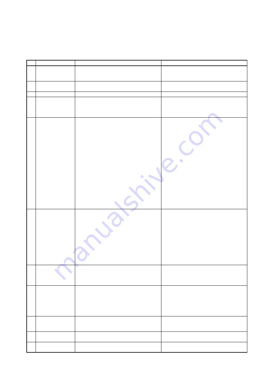
Appendix C Differences with MCX300 series
Main differences between MCX300 series and MCX514 are as follows.
For details of functions, please refer to each description in this manual.
Item
MCX300 series
MCX514
1
Treatment of
unused input pins
Can open.
(pulled up to VDD in the IC)
There are input pins not pulled up in the IC,
which should be connected to VDD or GND.
See chapter 5 for more details.
2
Width of reset signal
(RESETN)
Requires more than 4 CLK cycles
Requires more than 8 CLK cycles
3
Command reset
Writes 8000h (D15 bit
:1
) into WR0 register.
Writes 00FFh into WR0 register.
4
Setting of speed
parameter
Speed range setting is provided.
(multiple
:
1
~
500)
Speed parameter should be set based on the
actual value and multiple.
No speed range setting (speed range-free)
Speed parameter is set the actual value.
5
Fixed pulse driving
・
+ Direction fixed pulse driving
Specifies output pulse number as positive
value.
When executed, it drives specified pulses in
the + direction.
・
- Direction fixed pulse driving
Specifies output pulse number as positive
value.
When executed, it drives specified pulses in
the - direction.
・
Relative position driving
Specifies output pulse number as positive
value and when executed, it drives specified
pulses in the + direction.
Specifies output pulse number as negative
value and when executed, it drives specified
pulses in the - direction.
・
Counter relative position driving
Specifies output pulse number as positive
value and when executed, it drives specified
pulses in the - direction.
This is a driving command corresponding to -
direction fixed pulse driving of MCX300
series.
・
Absolute position driving
As the finish point of driving, specifies logical
position counter value that is a destination
point
6
RR2 register / Error
information display
(Software limit and
hardware limit
signal, alarm signal
from a servo driver
and emergency
stop signal)
Even though driving stops, if error factor
becomes active, error information bit becomes
1. And when error factor is cleared, error
information bit returns to 0.
If error factor becomes active during the driving
(or error factor is active at the start of driving),
error information bit becomes 1 and will keep 1
even after error factor is cleared.
If error factor becomes active while driving
stops, it does not error.
All the bits of RR2 return to 0 by error/finishing
status clear command (79h) or the start of next
driving. However, when an error occurs during
interpolation driving, it is necessary to write
error/finishing status clear command (79h).
7
Enable / disable of
hardware limit
function
Function of hardware limit signals (nLMTP and
nLMTM) (LMT+ and LMT- in MCX305) cannot be
disabled.
Function of hardware limit signals (nLMTP and
nLMTM) can be enabled / disabled.
8
Setting of software
limit value
Sets software limit value to compare register
(COMP+, COMP-)
Because of this, when using compare register as
software limit, the other function of compare
register cannot be used.
Sets software limit value to a dedicated register
(SLMT+, SLMT-).
9
Stop type of
software limit
Only decelerating stop
Selectable from decelerating stop or instant
stop.
10
Trapezoid triangle
form prevention
At reset
:
Disabled
At reset
:
Enabled
11
Acceleration
counter offsetting
At reset
:
8
At reset
:
0


