


NOVA electronics Inc.
MCX514 -
106
-
106
-
■
Encoder Pulse Input Type Setting
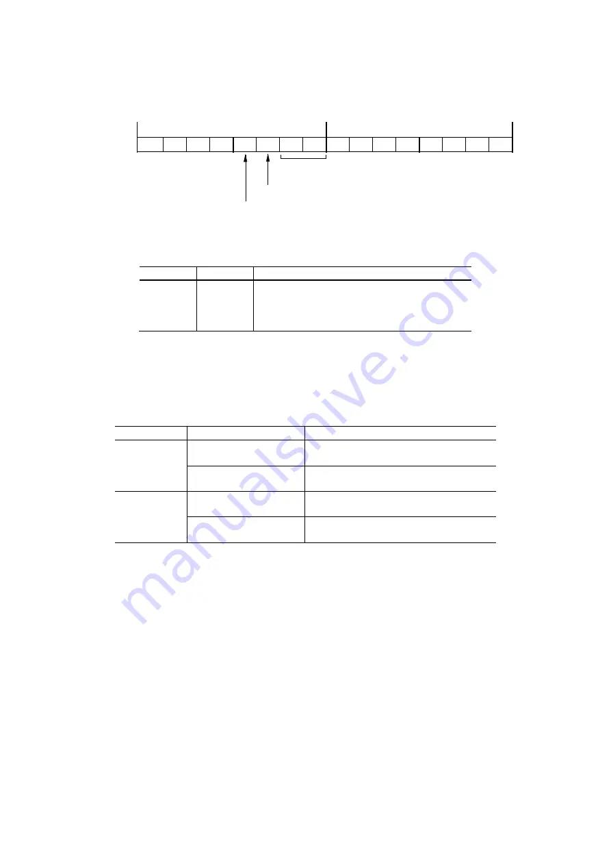
Encoder pulse input type can be set by D8, 9 bits (PIMD0, 1) of WR3 register.
Encoder pulse
input type
Logical level of encoder input signal
Replacing input pins of encoder input signal
D7
D6
D5
D4
H
L
D15
D14
D13
D12
D11
D10
D9
D8
D3
D2
D1
D0
WR3
PIMD0
PIMD1
PI-L
PIINV
The encoder pulse input type corresponding to each bit is as follows.
Table 2.12-4 Encoder pulse input type
D9(PIMD1)
D8(PIMD0)
Encoder pulse input type
0
0
Quadrature pulses input and quad edge evaluation
0
1
Quadrature pulses input and double edge evaluation
1
0
Quadrature pulses input and single edge evaluation
1
1
Up / Down pulse input
And it sets the logical level of an encoder input signal by D10 bit (PI-L) and sets whether the input pins of an encoder pulse input
are replaced or not by D11 bit (PIINV).
The increase/decrease of the real position counter due to replacing input pins of an encoder input signal as shown in the table
below.
Table 2.12-5 Increase/Decrease of Real Position Counter due to Replacing Input Pins of Encoder Input Signal
WR3/D11(PIINV)
Pulse input mode
Increase/decrease of real position counter
0
quadrature pulses mode
Count UP when the A phase is advancing.
Count DOWN when the B phase is advancing.
Up / Down pulse mode
Count UP at nPPIN pulse input.
Count DOWN at nPMIN pulse input.
1
quadrature pulses mode
Count UP when the B phase is advancing.
Count DOWN when the A phase is advancing.
Up / Down pulse mode
Count UP at nPMIN pulse input.
Count DONW at nPPIN pulse input.
2.12.4 Hardware Limit Signals
Hardware limit signals, nLMTP and nLMTM
, are used for stopping the pulse output if the limit sensors of + and − directions are
triggered.
The user can set to enable/disable a limit signal and set the logical level of a limit signal, and set whether to perform decelerating
stop or instant stop when a limit signal becomes active, and select whether to replace input pins of hardware limit input signals.
Enable/disable of a limit signal, the logical level of a limit signal and the stop type can be set by D12~10 bits of WR2 register. For
more details of the WR2 register, see chapter 6.6.
Whether to replace input pins of hardware limit input signals or not can be set by D12 bit (LMINV) of WR3 register. For more
details of the WR3 register, see chapter 6.7.
The status of a limit signal can be read out from RR3 register Page0 anytime.


