99
The Workstation Installation/Operation Manual Version 2 Document 51540 Rev. B1 4/8/02
3.4.9 Creating a Device Symbol
UniNet includes a comprehensive library of
device symbols, however custom symbols may
be created by the user for library inclusion.
These symbols must be created off-line using
any graphic design package or imported from
another source and saved in bitmap (.bmp)
format. This description uses Windows Paint.
To create a new device symbol:
1. Launch Paint from the
Start,
Programs, Accessories
menu in
Windows.
2. Using
Paint
, draw the new device
symbol. The symbol size should be
approximately 53 pixels by 53 pixels.
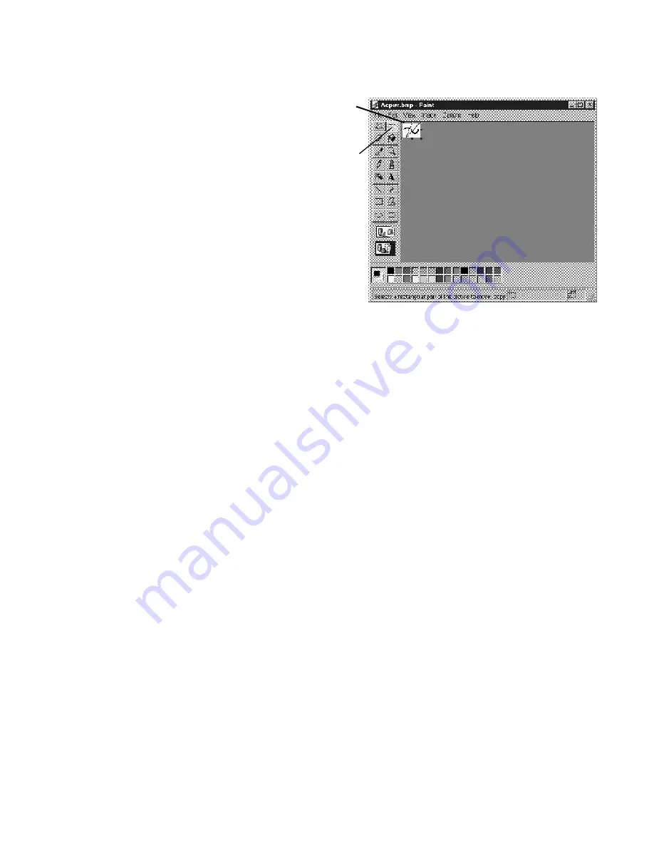
3. When finished, use the selection tool
to draw a box closely encompassing
the device (see figure 3-33).
4. With the device selected, select
Copy
To...
from the
Edit
menu. This
opens the
Copy To
dialog.
5. Save the file as a 16-color bitmap with a unique logical name.
Be sure to save the file to the
c:\uninet\ws\devices
directory.
Normal and Alarm State Symbols
Addressable devices have the ability to change state during an off-normal event. This means that the symbol
changes from a normal state to an alarm state. This requires two symbols assigned to the same device, one for the
normal state and one for the alarm state. Dual state device symbols for addressable devices are optional. They are
required only if you wish the device's appearance to change during an off-normal event.
To create an alarm state symbol to pair with a newly created normal symbol:
1. Open the normal device symbol in Paint.
2. Make changes to reflect the alarm state appearance.
3. Select
File, Save As...
and save the new version with the same name but, with
(Alarm)
at the end of
the name.
Example:
Normal symbol file name = bell.bmp
Alarm symbol file name = bell(Alarm).bmp
Be sure to save the file to the
c:\uninet\ws\devices
directory.
Device Masks
Device masks are layering tools which allow the background of a device symbol to be transparent so that it doesn't
block the floor plan.
To create a mask for the new device symbol:
1. Open the new device symbol in Paint.
2. Fill the object with black and leave the white background.
3. Select
File, Save As...
and save the new version with the same name but with a
.msk
extension.
Be sure to save the file to the
c:\uninet\ws\devices
directory. This must be done for the normal state symbol
and the alarm state symbol.
Figure 3-33: Using the
Selection Tool to Create a
Box
Selection Tool
Selection Box
Summary of Contents for UniNet 2000
Page 14: ...14 The Workstation Installation Operation Manual Version 2 Document 51540 Rev B1 4 8 02 NOTES...
Page 36: ...36 The Workstation Installation Operation Manual Version 2 Document 51540 Rev B1 4 8 02 NOTES...
Page 62: ...62 The Workstation Installation Operation Manual Version 2 Document 51540 Rev B1 4 8 02 NOTES...
Page 86: ...86 The Workstation Installation Operation Manual Version 2 Document 51540 Rev B1 4 8 02 NOTES...
Page 102: ...102 The Workstation Installation Operation Manual Version 2 Document 51540 Rev B1 4 8 02 NOTES...
Page 118: ...118 The Workstation Installation Operation Manual Version 2 Document 51540 Rev B1 4 8 02 NOTES...
Page 122: ...122 The Workstation Installation Operation Manual Version 2 Document 51540 Rev B1 4 8 02 NOTES...
Page 128: ...128 The Workstation Installation Operation Manual Version 2 Document 51540 Rev B1 4 8 02 NOTES...
Page 130: ...130 The Workstation Installation Operation Manual Version 2 Document 51540 Rev B1 4 8 02 NOTES...
Page 136: ...136 The Workstation Installation Operation Manual Version 2 Document 51540 Rev B1 4 8 02 NOTES...
Page 150: ...150 The Workstation Installation Operation Manual Version 2 Document 51540 Rev B1 4 8 02 NOTES...
Page 168: ...168 The Workstation Installation Operation Manual Version 2 Document 51540 Rev B1 4 8 02 Notes...
Page 170: ...170 The Workstation Installation Operation Manual Version 2 Document 51540 Rev B1 4 8 02 NOTES...
Page 186: ...186 The Workstation Installation Operation Manual Version 2 Document 51540 Rev B1 4 8 02 NOTES...
Page 197: ...197 The Workstation Installation Operation Manual Version 2 Document 51540 Rev B1 4 8 02 NOTES...
Page 198: ...198 The Workstation Installation Operation Manual Version 2 Document 51540 Rev B1 4 8 02 NOTES...
Page 199: ...199 The Workstation Installation Operation Manual Version 2 Document 51540 Rev B1 4 8 02 NOTES...


