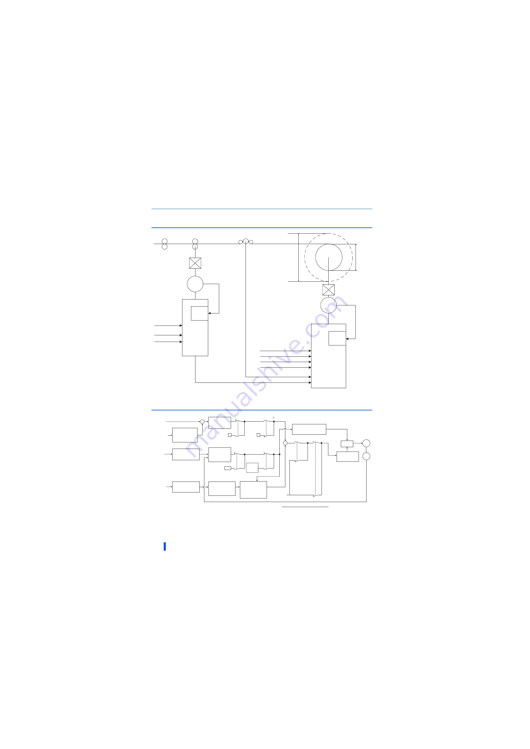
System configuration example
98
TENSION SENSOR FEEDBACK SPEED CONTROL
4.2
System configuration example
4.3
Control block diagram
FR-A800-R2R
For winding roll (
Pr.1230
= 0)
Encoder
Line speed command
Tension sensor
Tension feedback
Minimum
diameter
Maximum
diameter
AM
2 (
Pr.361
= 3)
1 (
Pr.363
= 5)
STF/STR
Start signal
Dancer/tension control selection
X114 (
Pr.180
= 114)
FR-A8AP
Encoder
Line speed command
FR-A800-R2R
FR-A8AP
M
M
X117 (
Pr.182
= 117)
Winding length clear
X109 (
Pr.181
= 109)
Stored winding diameter clear
2
Line speed
command
STF/STR
Start signal
Dancer/tension
control selection
X114
Pr.363
= 9999
PID action
set point
(
Pr.133
)
Actual
line speed
Line speed
command
Frequency
setting
Winding diameter
compensation
speed generation
Conversion from line
speed to frequency
Winding diameter
compensation
speed
∗1
Winding diameter
∗2
After clearing, the value becomes the minimum winding diameter when
Pr.1230
= "0" (winding),
and the maximum winding diameter when
Pr.1230
= "1" (unwinding).
Motor speed
+
-
PID operation
Pr.129, Pr.130,
Pr.134
X116-OFF
X116-ON
X109-OFF
X109-ON
X115-OFF
X115-ON
Held
Winding
diameter
clear
∗2
0
0
+
+
Speed control proportional
gain compensation
Pr.639 to Pr.644
Speed
control
Acceleration
/deceleration
Pr.7, Pr.8
= 0
M
Encoder
Pr.128
= 40, 41
X114-ON
X114-OFF
Pr.128
= 0
Dancer signal /
tension feedback
input selection
Pr.363
Line speed
command selection
Pr.361
Actual line speed
input selection
Pr.362
Winding diameter
calculation
Pr.1235, Pr.1236,
Pr.1243, Pr.1244
Line speed command
Acceleration
/deceleration
Pr.394, Pr.395
Tension
feedback
Pr.363
= 9999
Line speed command
∗1
Winding diameter compensation speed =
π
× Winding diameter × Gear ratio
Summary of Contents for A800 Plus Series
Page 240: ...239 MEMO ...


