background image

Dancer feedback speed control details

DANCER FEEDBACK SPEED CONTROL

65

3

Line speed command input by parameter setting (Pr.361 = "8")

 • The value set in 

Pr.360 Line speed command value

 is used for the line speed command. (Setting range: 0 to 6553.4 m/

min)

Line speed command input through RS-485/Ethernet or using a 
communication option (except for the FR-A8ND)

 • Use the read/write procedure for the set frequency to read/write the line speed command value through RS-485 / Ethernet 

(CC-Link IE Field Network Basic) or using a communication option (FR-A8NC/FR-A8NCE/FR-A8NP). The frequency set for 
normal speed control is used as the line speed command value for dancer feedback speed control. (The setting is used as 
the set frequency when the X114 signal is OFF, and used as the line speed command value when the X114 signal is ON.)

 • The setting range is H0000 to HFFFE (0 to 6553.4), and the setting increment is 0.1.

NOTE

 • For the details of RS-485 communication, refer to the FR-A800 Instruction Manual (Detailed). For the details of CC-Link IE 

Field Network Basic, refer to the Ethernet Function Manual. For the details of communication options, refer to the Instruction 
Manual of each option.

Line speed command input using the FR-A8ND

 • The line speed command value is read/written as follows.

 • The line speed command value is written through I/O communication (output instance 127) as follows.

 • The message communication (instance 1 in class 0x2A) related to the line speed command value is defined as follows.

NOTE

 • Output instances 20, 21, and 126 and input instances 70, 71, and 176 are not available for the line speed command.
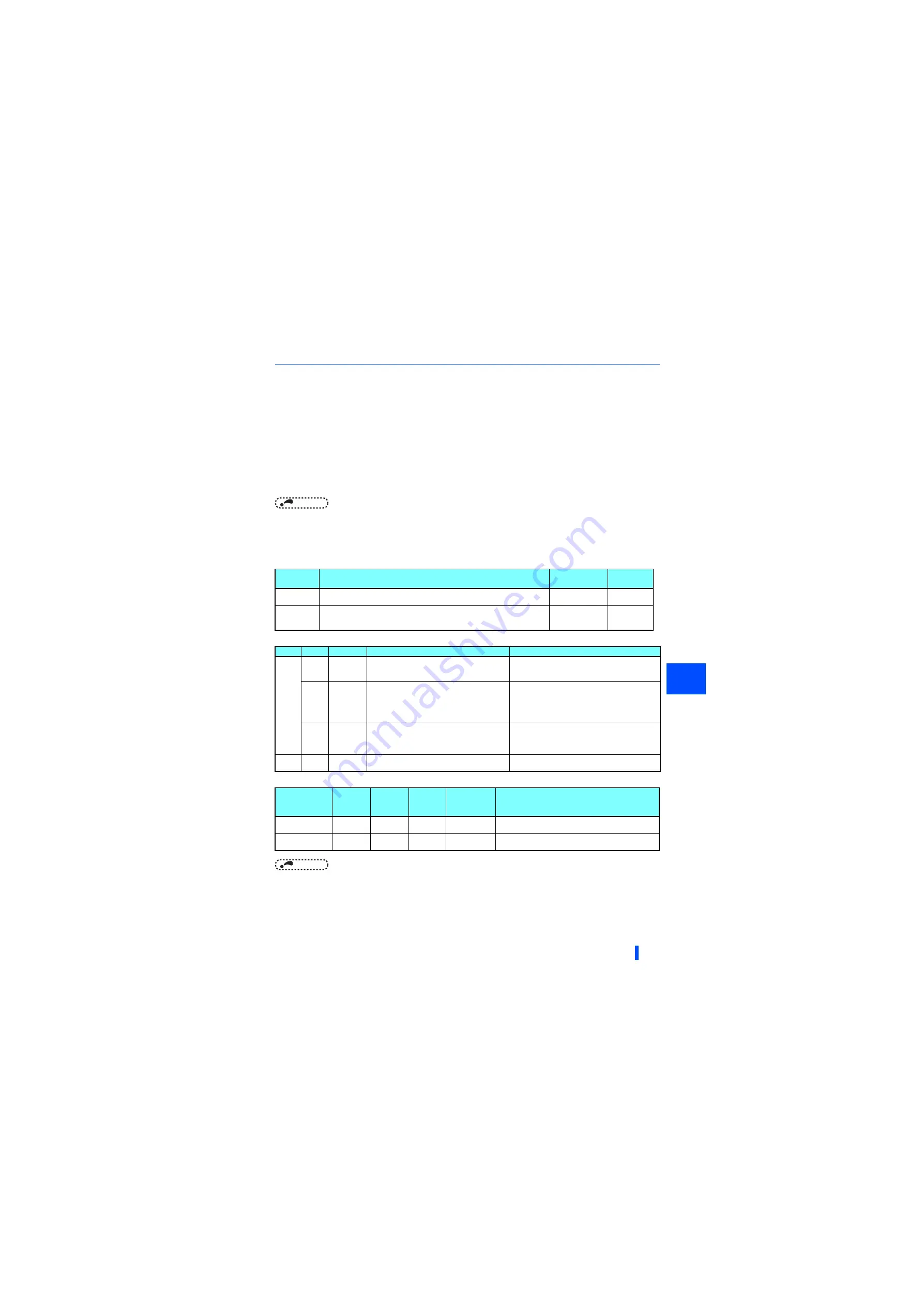
Read/write

Reading/writing method for line speed command

Setting range

Setting 

increments

Read

• Read the 

Pr.360

 setting.

H0000 to HFFFE
(0 to 6553.4)

0.1 m/min

Write

• Writing through I/O communication (Output instance 127).
• Write through message communication.
• Write in 

Pr.360

.

H0000 to HFFFE
(0 to 6553.4)

0.1 m/min

Byte

Bit

Function

Setting method

Remarks

1

5

Write Attr

0: The values set in bytes 2 and 3 are used as the 
speed/frequency setting value.

1: The values set in bytes 2 and 3 are used as the 
writing data to the attributes specified in bytes 6 and 
7, respectively.

6

Hz

1: 0.01 Hz increment

0: An unexpected value is written. (The value written 
in byte 2 and byte 3 is recognized as a number of 
rotations. Then, the value is converted into a 
frequency value and written as the line speed 
command value.)

7

32-bit 
format

0: The format for 16-bit data is being selected.
(Bytes 2 and 3 are used.)
1: The format for 32-bit data is being selected.
(Bytes 2 to 5 are used.)

2, 3

Speed
setting

The line speed command value is written.

According to the setting of bit 7 in byte 1, the format 
is selected for 16-bit data or 32-bit data.

Attribute ID

Access

Data

type

Number 

of data 

bytes

Range

Description

112

Set

UINT

2

0 to 0xFFFE
(0 to 6553.4)

The line speed command value is written in RAM. 
(0.1 increments)

113

Set

UINT

2

0 to 0xFFFE
(0 to 6553.4)

The line speed command value is written in EEPROM. 
(0.1 increments)

Summary of Contents for A800 Plus Series

Page 1: ...s the functions dedicated to the FR A800 R2R inverter For the functions not found in this Function Manual refer to the Instruction Manual of the FR A800 inverter In addition to this Roll to Roll Function Manual please read the Instruction Manual of the FR A800 inverter carefully Do not use this product until you have a full knowledge of the equipment safety information and instructions Please forw...

Page 2: ...r feedback speed control details 58 3 5 1 Dancer feedback speed control function selection 58 3 5 2 Winding unwinding shaft selection 59 3 5 3 Line speed command input 60 3 5 4 Compensation for line speed command input 66 3 5 5 Acceleration deceleration time setting for line speed command 69 3 5 6 Dancer roll setting 71 3 5 7 Dancer roll position detection 73 3 5 8 PID offset displacement 73 3 5 9...

Page 3: ... procedure 112 5 5 Tension sensorless torque control details 117 5 5 1 Tension sensorless torque control setting method 117 5 5 2 Input method of tension command 118 5 5 3 Torque generation direction setting 121 5 5 4 Taper function 124 5 5 5 Inertia compensation function 130 5 5 6 Mechanical loss compensation function 135 5 5 7 Stall mode function 137 6 TENSION SENSOR FEEDBACK TORQUE CONTROL 139 ...

Page 4: ...Winding diameter calculation using material thickness thickness method 166 8 2 5 Line speed at winding diameter calculated value activation 167 8 2 6 Averaging process for winding diameter calculation 168 8 2 7 Minimum maximum winding diameter 169 8 2 8 Winding diameter compensation speed filter 170 8 2 9 Target winding diameter achieved 171 8 2 10 Winding diameter calculation at a start 171 8 2 1...

Page 5: ...199 10 4 1 Dancer feedback speed control with roll diameter compensation for printers 199 10 4 2 Dancer feedback speed control with roll diameter compensation for wire drawing machines 204 10 4 3 Tension sensorless torque control with roll diameter compensation for printers 208 10 4 4 Tension sensor feedback torque control with roll diameter compensation for fabric inspection machines 212 10 5 Par...

Page 6: ...peed and the dancer roll position constant Tension sensor feedback speed control Speed control to keep the line speed and the tension sensor feedback constant Tension sensorless torque control Torque control to keep a constant tension on the workpiece without using a dancer roll and a tension controller Tension sensor feedback torque control Torque control to more accurately keep a constant tensio...

Page 7: ...trol function Winding diameter compensation function Abbreviation generic name Description DU Operation panel FR DU08 Operation panel Operation panel FR DU08 and LCD operation panel FR LU08 Parameter unit Parameter unit FR PU07 PU Operation panel and parameter unit Inverter Mitsubishi Electric FR A800 series inverter FR A800 R2R FR A800 R2R roll to roll dedicated inverter Vector control compatible...

Page 8: ...50 60 s inverse time characteristics Surrounding air temperature of 50 C Pr Name Pr 570 setting 0 1 2 initial value 3 12 0 Torque boost 1 1 1 1 1 7 Acceleration time 1 1 1 1 1 8 Deceleration time 1 1 1 1 1 9 Electronic thermal O L relay SLD rated current 2 LD rated current 2 ND rated current 2 3 HD rated current 2 3 SND rated current 2 12 DC injection brake operation voltage 1 1 1 1 1 22 Stall pre...

Page 9: ... 5K 00167 2 2K 00250 3 7K 00340 5 5K 00490 7 5K 00630 11K 00770 15K 00930 18 5K 01250 22K 01540 30K 01870 37K 02330 45K 03160 55K 03800 75K 04750 90K 400 V class FR A840 R2R 00023 0 4K 00038 0 75K 00052 1 5K 00083 2 2K 00126 3 7K 00170 5 5K 00250 7 5K 00310 11K 00380 15K 00470 18 5K 00620 22K 00770 30K 00930 37K 01160 45K 01800 55K 02160 75K 02600 90K or higher 0 0 1 6 4 4 4 3 3 2 2 2 2 2 2 1 5 1 ...

Page 10: ... 1 Description For the SND rating when the instantaneous load factor reaches or exceeds 155 of the inverter rated current while the output current average value is 50 or more of the inverter rated current the inverter trips Check point Check that acceleration deceleration time is not too short Check that torque boost setting is not too large small Check that load pattern selection setting is appro...

Page 11: ...02 Multi speed setting middle speed 0 to 590 Hz 0 01 Hz 30 Hz 17 6 D303 Multi speed setting low speed 0 to 590 Hz 0 01 Hz 10 Hz 17 7 F010 Acceleration time 0 to 3600 s 0 1 s 5 s 4 17 15 s 5 8 F011 Deceleration time 0 to 3600 s 0 1 s 5 s 4 17 15 s 5 9 H000 Electronic thermal O L relay 0 to 500 A 2 0 01 A 2 Inverter rated current 17 0 to 3600 A 3 0 1 A 3 10 G100 DC injection brake operation frequenc...

Page 12: ...n operation frequency 0 to 590 Hz 9999 0 01 Hz 0 Hz 17 50 M444 Second output frequency detection 0 to 590 Hz 0 01 Hz 30 Hz 17 51 H010 Second electronic thermal O L relay 0 to 500 A 9999 2 0 01 A 2 9999 17 0 to 3600 A 9999 3 0 1 A 3 52 M100 Operation panel main monitor selection 0 5 to 14 17 to 20 22 to 36 38 40 to 46 50 to 57 61 to 64 67 71 to 74 81 to 93 97 98 100 1 0 181 54 M300 FM CA terminal f...

Page 13: ...ant R1 0 to 50 Ω 9999 2 0 001 Ω 2 9999 17 0 to 400 mΩ 9999 3 0 01 mΩ 3 91 C121 Motor constant R2 0 to 50 Ω 9999 2 0 001 Ω 2 9999 17 0 to 400 mΩ 9999 3 0 01 mΩ 3 92 C122 Motor constant L1 0 to 6000 mH 9999 2 0 1 mH 2 9999 17 0 to 400 mH 9999 3 0 01 mH 3 93 C123 Motor constant L2 0 to 6000 mH 9999 2 0 1 mH 2 9999 17 0 to 400 mH 9999 3 0 01 mH 3 94 C124 Motor constant X 0 to 100 9999 0 1 2 9999 17 0 ...

Page 14: ...99 74 108 150 133 A611 PID action set point 400 to 600 0 01 500 71 106 R101 134 A615 PID differential time 0 01 to 10 s 9999 0 01 s 9999 84 R112 135 R161 Integral clamp positive polarity 0 to 100 9999 0 1 9999 85 136 R162 Integral clamp negative polarity 0 to 100 9999 0 1 9999 85 137 R163 PID upper lower limit hysteresis width 0 to 100 9999 0 1 9999 74 108 150 140 F200 Backlash acceleration stoppi...

Page 15: ... not set E080 169 E001 E081 170 M020 Watt hour meter clear 0 10 9999 1 9999 17 171 M030 Operation hour meter clear 0 9999 1 9999 17 172 E441 User group registered display batch clear 9999 0 to 16 1 0 17 173 E442 User group registration 0 to 1999 9999 1 9999 17 174 E443 User group clear 0 to 1999 9999 1 9999 17 178 T700 STF terminal function selection 0 to 13 16 to 18 20 23 to 28 32 42 to 44 46 to ...

Page 16: ...245 G203 Rated slip 0 to 50 9999 0 01 9999 17 246 G204 Slip compensation time constant 0 01 to 10 s 0 01 s 0 5 s 17 247 G205 Constant power range slip compensation selection 0 9999 1 9999 17 249 H101 Earth ground fault detection at start 0 1 1 0 17 250 G106 Stop selection 0 to 100 s 1000 to 1100 s 8888 9999 0 1 s 9999 17 251 H200 Output phase loss protection selection 0 1 1 1 17 252 T050 Override ...

Page 17: ...activation selection 0 1 2 10 11 20 to 22 1 0 17 289 M431 Inverter output terminal filter 5 to 50 ms 9999 1 ms 9999 17 290 M044 Monitor negative output selection 0 to 7 1 0 17 291 D100 Pulse train I O selection FM type 0 1 10 11 20 21 100 1 0 17 AM type 0 1 294 A785 UV avoidance voltage gain 0 to 200 0 1 100 17 295 E201 Frequency change increment amount setting 0 0 01 0 10 1 00 10 00 0 01 0 17 296...

Page 18: ...999 1 0 163 363 R102 Dancer tension sensor feedback input selection 3 to 6 9999 1 9999 71 106 149 364 R411 Dancer tension setting input selection 3 to 6 9999 1 9999 92 365 R302 Tension command value RAM 0 to 100 N 13 0 01 N 13 0 N 118 366 R303 Tension command value RAM EEPROM 0 to 100 N 13 0 01 N 13 0 N 118 367 9 G240 Speed feedback range 0 to 590 Hz 9999 0 01 Hz 9999 17 368 9 G241 Feedback gain 0...

Page 19: ... V 0 1 V 200 V 7 17 400 V 8 457 C205 Rated second motor frequency 10 to 400 Hz 9999 0 01 Hz 9999 17 458 C220 Second motor constant R1 0 to 50 Ω 9999 2 0 001 Ω 2 9999 17 0 to 400 mΩ 9999 3 0 01 mΩ 3 459 C221 Second motor constant R2 0 to 50 Ω 9999 2 0 001 Ω 2 9999 17 0 to 400 mΩ 9999 3 0 01 mΩ 3 460 C222 Second motor constant L1 0 to 6000 mH 9999 2 0 1 mH 2 9999 17 0 to 400 mH 9999 3 0 01 mH 3 461 ...

Page 20: ...17 498 A804 PLC function flash memory clear 0 9696 0 to 9999 1 0 17 502 N013 Stop mode selection at communication error 0 to 2 11 12 1 0 17 503 E710 Maintenance timer 1 0 1 to 9998 1 0 17 504 E711 Maintenance timer 1 warning output set time 0 to 9998 9999 1 9999 17 505 M001 Speed setting reference 1 to 590 Hz 0 01 Hz 60 Hz 50 Hz 17 516 F400 S pattern time at a start of acceleration 0 1 to 2 5 s 0 ...

Page 21: ...tation excitation current low speed scaling factor 0 to 300 9999 0 1 9999 17 620 R570 Line speed bias for reel change 0 to 2000 m min 11 0 1 m min 11 1000 m min 11 90 621 R423 Allowable deviation from target line speed 0 to 6553 4 m min 11 0 1 m min 11 0 m min 11 69 90 622 R204 Line speed command for starting 0 to 6553 4 m min 11 0 1 m min 11 0 m min 11 60 635 R214 Line speed command added compens...

Page 22: ... 9998 1 0 17 687 E713 Maintenance timer 2 warning output set time 0 to 9998 9999 1 9999 17 688 E714 Maintenance timer 3 0 1 to 9998 1 0 17 689 E715 Maintenance timer 3 warning output set time 0 to 9998 9999 1 9999 17 690 H881 Deceleration check time 0 to 3600 s 9999 0 1 s 1 s 17 692 H011 Second free thermal reduction frequency 1 0 to 590 Hz 9999 0 01 Hz 9999 17 693 H012 Second free thermal reducti...

Page 23: ...400 9999 0 1 9999 17 816 H720 Torque limit level during acceleration 0 to 400 9999 0 1 9999 17 817 H721 Torque limit level during deceleration 0 to 400 9999 0 1 9999 17 818 C112 Easy gain tuning response level setting 1 to 15 1 2 17 819 C113 Easy gain tuning selection 0 to 2 1 0 17 820 G211 Speed control P gain 1 0 to 1000 1 60 17 821 G212 Speed control integral time 1 0 to 20 s 0 001 s 0 333 s 17...

Page 24: ...194 863 9 M600 Control terminal option Encoder pulse division ratio 1 to 32767 1 1 17 864 M470 Torque detection 0 to 400 0 1 150 17 865 M446 Low speed detection 0 to 590 Hz 0 01 Hz 1 5 Hz 17 866 M042 Torque monitoring reference 0 to 400 0 1 150 17 867 M321 AM output filter 0 to 5 s 0 01 s 0 01 s 17 868 T010 Terminal 1 function assignment 0 to 6 9999 1 0 17 869 M334 Current output filter 0 to 5 s 0...

Page 25: ...0 1 9999 17 C0 900 10 M310 FM CA terminal calibration 17 C1 901 10 M320 AM terminal calibration 17 C2 902 10 T200 Terminal 2 frequency setting bias frequency 0 to 590 Hz 0 01 Hz 0 Hz 17 C3 902 10 T201 Terminal 2 frequency setting bias 0 to 300 0 1 0 17 125 903 10 T202 Terminal 2 frequency setting gain frequency 0 to 590 Hz 0 01 Hz 60 Hz 50 Hz 17 C4 903 10 T203 Terminal 2 frequency setting gain 0 t...

Page 26: ...etic flux 0 to 400 0 1 150 17 C41 933 10 T413 Terminal 4 gain torque magnetic flux 0 to 300 0 1 100 17 977 E302 Input voltage mode selection 0 1 1 0 17 989 E490 Parameter copy alarm release 10 2 1 10 2 17 100 3 100 3 990 E104 PU buzzer control 0 1 1 1 17 991 E105 PU contrast adjustment 0 to 63 1 58 17 992 M104 Operation panel setting dial push monitor selection 0 to 3 5 to 14 17 to 20 22 to 36 38 ...

Page 27: ... source selection 3ch 203 181 1030 A913 Analog source selection 4ch 204 181 1031 A914 Analog source selection 5ch 205 181 1032 A915 Analog source selection 6ch 206 181 1033 A916 Analog source selection 7ch 207 181 1034 A917 Analog source selection 8ch 208 181 1035 A918 Analog trigger channel 1 to 8 1 1 17 1036 A919 Analog trigger operation selection 0 1 1 0 17 1037 A920 Analog trigger level 600 to...

Page 28: ...0 s 71 106 149 1230 R002 Winding unwinding selection 0 1 1 0 59 135 149 1231 R010 Material thickness d1 0 to 20 mm 9999 0 001 mm 9999 166 1232 R011 Material thickness d2 0 to 20 mm 0 001 mm 1 mm 166 1233 R012 Material thickness d3 0 to 20 mm 0 001 mm 1 mm 166 1234 R013 Material thickness d4 0 to 20 mm 0 001 mm 1 mm 166 1235 R020 Maximum winding diameter 1 1 to 6553 mm 1 mm 2 mm 169 1236 R021 Minim...

Page 29: ...72 R237 Line multi speed setting speed 8 0 to 6553 4 m min 11 0 1 m min 11 0 m min 11 60 1273 R238 Line multi speed setting speed 9 0 to 6553 4 m min 11 0 1 m min 11 0 m min 11 60 1274 R239 Line multi speed setting speed 10 0 to 6553 4 m min 11 0 1 m min 11 0 m min 11 60 1275 R240 Line multi speed setting speed 11 0 to 6553 4 m min 11 0 1 m min 11 0 m min 11 60 1276 R241 Line multi speed setting s...

Page 30: ...06 R340 Commanded tension reduction scaling factor during stall condition 0 to 200 0 1 20 137 1407 R341 Speed limit during stall condition 0 to 60 Hz 0 01 Hz 1 Hz 137 1409 R343 Tension command cushion time during stall condition 0 to 360 s 9999 0 01 s 9999 137 1410 R530 Motor inertia 0 to 500 kg m2 9999 0 01 kg m2 0 kg m2 130 1411 R531 Empty reel inertia 0 to 500 kg m2 9999 0 01 kg m2 0 kg m2 130 ...

Page 31: ...rd models 15 The initial value is for separated converter types 16 The setting is available only when the FR A8AZ is installed 17 For the details refer to the Instruction Manual Detailed of the FR A800 inverter in the enclosed CD ROM 18 For the details refer to the Instruction Manual of the FR A8AL 1428 R559 Mechanical loss setting frequency 5 0 to 400 Hz 9999 0 01 Hz 9999 135 1429 R560 Mechanical...

Page 32: ...pulse input bias 163 R056 283 Actual line speed pulse input gain 163 R057 284 Actual line speed input filter time constant 163 R070 1252 Dancer lower limit position 171 R071 1253 Initial winding diameter calculation deadband 171 R072 1254 Initial winding diameter calculation deadband 2 171 R073 1255 Accumulated amount 171 R074 1256 Speed control P gain at start 171 R075 1257 Speed control integral...

Page 33: ... speed setting speed 6 60 Pr group Pr Name Refer to page R236 1271 Line multi speed setting speed 7 60 R237 1272 Line multi speed setting speed 8 60 R238 1273 Line multi speed setting speed 9 60 R239 1274 Line multi speed setting speed 10 60 R240 1275 Line multi speed setting speed 11 60 R241 1276 Line multi speed setting speed 12 60 R242 1277 Line multi speed setting speed 13 60 R243 1278 Line mu...

Page 34: ... time for inertia compensation 130 R537 271 Second acceleration time for inertia compensation 130 R538 272 Second deceleration time for inertia compensation 130 R539 753 Empty reel inertia integer 130 R540 754 Empty reel inertia exponent 130 R550 1419 Mechanical loss setting frequency bias 135 R551 1420 Mechanical loss setting frequency 1 135 R552 1421 Mechanical loss 1 135 Pr group Pr Name Refer ...

Page 35: ...celeration deceleration time 6 F021 45 Second deceleration time 6 F022 147 Acceleration deceleration time switching frequency 6 F030 110 Third acceleration deceleration time 6 F031 111 Third deceleration time 6 F040 1103 Deceleration time at emergency stop 150 Pr group Pr Name Refer to page F100 29 Acceleration deceleration pattern selection 6 F102 13 Starting frequency 6 F103 571 Holding time at ...

Page 36: ...waiting time 6 Pr group Pr Name Refer to page H303 69 Retry count display erase 6 H400 1 Maximum frequency 6 H401 2 Minimum frequency 6 H402 18 High speed maximum frequency 6 H410 807 Speed limit selection 6 H411 808 Forward rotation speed limit speed limit 6 H412 809 Reverse rotation speed limit reverse side speed limit 6 H414 1113 Speed limit method selection 6 H415 873 1 Speed limit 6 H416 285 ...

Page 37: ...lection 1 181 M102 775 Operation panel monitor selection 2 181 M103 776 Operation panel monitor selection 3 181 M104 992 Operation panel setting dial push monitor selection 181 M200 892 Load factor 6 Pr group Pr Name Refer to page M201 893 Energy saving monitor reference motor capacity 6 M202 894 Control selection during commercial power supply operation 6 M203 895 Power saving rate reference valu...

Page 38: ...pensation amount terminal 4 6 T042 126 Terminal 4 frequency setting gain frequency 6 T050 252 Override bias 66 T051 253 Override gain 66 T052 573 4 mA input check selection 6 T054 778 4 mA input check filter 6 T100 C12 917 2 Terminal 1 bias frequency speed 6 T101 C13 917 2 Terminal 1 bias speed 6 Pr group Pr Name Refer to page T102 C14 918 2 Terminal 1 gain frequency speed 6 T103 C15 918 2 Termina...

Page 39: ...econd motor constant R1 6 C221 459 Second motor constant R2 6 C222 460 Second motor constant L1 6 C223 461 Second motor constant L2 6 C224 462 Second motor constant X 6 C225 455 Second motor excitation current 6 Pr group Pr Name Refer to page C226 860 Second motor torque current Rated PM motor current 6 C240 851 1 Control terminal option Number of encoder pulses 6 C241 852 1 Control terminal optio...

Page 40: ...003 422 Position control gain 6 B009 428 Command pulse selection 60 Pr group Pr Name Refer to page N000 549 Protocol selection 6 N001 342 Communication EEPROM write selection 6 N002 539 MODBUS RTU communication check time interval 6 Pr group Pr Name Refer to page N013 502 Stop mode selection at communication error 6 N020 117 PU communication station number 6 N021 118 PU communication speed 6 N022 ...

Page 41: ...r 1 6 G216 827 Torque detection filter 1 6 G217 854 Excitation ratio 6 G218 1115 Speed control integral term clear time 6 G220 877 Speed feed forward control model adaptive speed control selection 6 G221 878 Speed feed forward filter 6 G222 879 Speed feed forward torque limit 6 G223 881 Speed feed forward gain 6 G224 828 Model speed control gain 6 G230 840 Torque bias selection 6 G231 841 Torque b...

Page 42: ...ilable Winding diameter calculation Calculation based on the line speed detection and the motor rotation speed and calculation based on the material thickness and the number of motor rotations are selectable Actual line speed detection Pulse train input A B phase single phase and analog input are selectable Reduction ratio setting Available Maximum minimum winding diameter setting Available Four p...

Page 43: ...winding diameter when Pr 1230 0 winding and the maximum winding diameter when Pr 1230 1 unwinding X116 OFF X116 ON X109 OFF X109 ON X115 OFF X115 ON Held Winding diameter clear 2 0 0 Speed control proportional gain compensation Pr 639 to Pr 644 M Encoder X114 ON X114 OFF Dancer signal tension feedback input selection Pr 363 PID action set point Pr 133 Dancer roll position Actual line speed Line sp...

Page 44: ... 363 Actual line speed input Pr 362 Tension command input Pr 804 Line speed command input Pr 361 0 Taper setting input Pr 1285 Dancer tension setting input Pr 364 Line speed command compensation input Line speed command input Pr 361 0 Speed command during speed control When Pr 361 Line speed command input selection 0 while tension sensorless torque control is valid the line speed command is input ...

Page 45: ... method for regenerative driving in low speed range about 10 Hz or lower For the parameter details refer to the FR A800 Instruction Manual Detailed 3 Offline auto tuning Perform offline auto tuning as required For offline auto tuning refer to page 49 After the offline auto tuning perform the test run of the motor alone to make sure that no fault is found in the motor s behavior 4 Speed control gai...

Page 46: ... per roll diameter calculation 1243 Gear ratio numerator follower side 1 Set a gear ratio when the motor shaft has a reduction gear The increment is 1 for each parameter 1244 Gear ratio denominator driver side 1 7 Acceleration time 0 s 8 Deceleration time 0 s 394 First acceleration time for line speed command 1 Setting is required in 0 1 second increments when the cushion time is not considered fo...

Page 47: ...5 Terminal 1 analog value 100 to 100 0 to 10 VDC 2 Refer to page 64 6 Terminal 6 FR A8AZ analog value 100 to 100 0 to 10 VDC 2 Refer to page 64 7 FR A8AL single phase pulse train input PP NP Refer to page 63 8 Line speed command according to the Pr 360 setting Refer to page 65 9999 initial value No function Item Setting example 1 Setting example 2 Line speed command input method Setting by analog ...

Page 48: ...65 7 FR A8AL single phase pulse train input PP NP Refer to page 164 9999 No function Item Setting example 1 Setting example 2 Actual line speed input method Setting by analog current 4 to 20 mA input through terminal 4 Pr 362 4 Setting by pulse train input through terminal JOG Pr 362 1 Parameter setting Pr 280 Actual line speed voltage current bias 20 Pr 281 Actual line speed bias 0 m min Pr 278 A...

Page 49: ...oll to the minimum diameter roll and vice versa and check that no fault is found in the system behavior Item Setting example 1 Setting example 2 Target position setting method Setting the target position in the middle between the upper and lower limits Setting the target position directly Parameter setting Set Pr 52 86 terminal 1 input voltage monitor in and record the value when the dancer positi...

Page 50: ... auto tuning is not performed correctly when the surge voltage suppression filter FR ASF H FR BMF H is inserted between the inverter and motor Be sure to remove them before performing tuning Make sure to connect the encoder to the motor without coaxial misalignment during vector control Set the speed ratio to 1 1 Setting To perform tuning set the following parameters about the motor 1 Differs acco...

Page 51: ... mH and A unit setting Motor constant parameterinternal data setting Motor constant parameter Ω mΩ and A unit setting Mitsubishi Electric standard motor Mitsubishi Electric high efficiency motor SF JR SF TH 0 initial value 3 4 SF JR 4P 1 5 kW or lower 20 23 24 SF HR 40 43 44 Others 0 initial value 3 4 Mitsubishi Electric constant torque motor SF JRCA 4P SF TH constant torque 1 13 14 SF HRCA 50 53 ...

Page 52: ...steps from FM CA and AM Do not perform ON OFF switching of the Second function selection RT signal during offline auto tuning Auto tuning will not be performed properly Setting offline auto tuning Pr 96 Auto tuning setting status 1 or 101 will make pre excitation invalid When the offline auto tuning is selected Pr 96 Auto tuning setting status 101 the motor rotates Take caution and ensure the safe...

Page 53: ...ning Offline auto tuning setting Time No motor rotation Pr 96 1 Approx 25 to 120 s The time depends on the inverter capacity and motor type With motor rotation Pr 96 101 Approx 40 s The following offline auto tuning time is set according to the acceleration deceleration time setting Offline auto tuning time Acceleration time Deceleration time Approx 30 s Error display Error cause Countermeasures 8...

Page 54: ...r feedback is calculated automatically from the load inertia ratio and the response level the work required for gain adjustment is reduced Easy gain tuning The load inertia ratio can be entered manually if you already know the ratio Manual gain adjustment is useful for achieving optimum machine performance or improving unfavorable conditions such as vibration and acoustic noise during operation wi...

Page 55: ...e automatically set final Pr 820 value in Pr 641 Speed control proportional gain 1 5 Installation of the maximum diameter roll Install the maximum diameter roll 6 Tuning with the maximum diameter roll Perform easy gain tuning in the same way used for the tuning with the minimum diameter roll Take a note of the Pr 820 value and set it in Pr 644 Speed control proportional gain 4 Vector control Real ...

Page 56: ...e following calculation in Pr 643 Speed control proportional gain 3 3 Set the diameters of the medium diameter rolls Medium diameter roll 1 Pr 639 Speed control proportional term applied diameter 1 Medium diameter 1 Minimum diameter Maximum diameter Minimum diameter 100 Medium diameter roll 2 Pr 640 Speed control proportional term applied diameter 2 Medium diameter 2 Minimum diameter Maximum diame...

Page 57: ...me way used for the tuning with the minimum diameter roll Then set the Pr 820 value in Pr 644 6 Calculation of the medium diameter gain With medium diameter roll No medium diameter roll 1 Tuning with the medium diameter roll 1 Adjust the Pr 820 setting in the same way used for the tuning with the minimum diameter roll Then set the Pr 820 value in Pr 642 Set the result of the following calculation ...

Page 58: ...ershooting occurs once or so before the dancer roll returns to the set position Refer to the following according to the dancer roll condition NOTE Set Pr 134 PID differential time only when it is necessary as it causes hunting However set a small value in Pr 134 to cease fluctuation of the dancer roll by disturbance and such at an early point Set 0 01 s at first and gradually increase the value St...

Page 59: ...eed command input selection P R200 Pr 361 60 To select a unit of the line speed Line speed unit P R201 Pr 358 60 To input the line speed command using multi speed setting Line multi speed setting P R230 to P R244 Pr 1265 to Pr 1279 60 To calibrate the line speed command value Line speed command bias gain P R210 to P R213 P R220 to P R223 Pr 350 to Pr 357 60 To set the line speed command to start o...

Page 60: ...he X18 signal set 116 in any of Pr 178 to Pr 189 input terminal function selection to assign the function 3 5 2 Winding unwinding shaft selection Select whether the target roll is a winding shaft or unwinding shaft Winding unwinding selection Pr 1230 Use Pr 1230 Winding unwinding selection to select whether the target roll is a winding shaft or unwinding shaft The initial diameter of the winding s...

Page 61: ...35 0 to 65535 Set the gain line speed command value for pulse train input 358 R201 Line speed unit 0 0 m min 1 m s 2 mm min 3 mm s 360 R202 Line speed command value 0 m min 1 0 to 6553 4 m min 1 Set the line speed command value 361 R200 Line speed command input selection 9999 0 According to the priority of the speed command sources 1 Terminal JOG single phase pulse train input 2 FR A8AP FR A8AL FR...

Page 62: ...eed setting speed 7 0 m min 1 0 to 6553 4 m min 1 1272 R237 Line multi speed setting speed 8 0 m min 1 0 to 6553 4 m min 1 1273 R238 Line multi speed setting speed 9 0 m min 1 0 to 6553 4 m min 1 1274 R239 Line multi speed setting speed 10 0 m min 1 0 to 6553 4 m min 1 1275 R240 Line multi speed setting speed 11 0 m min 1 0 to 6553 4 m min 1 1276 R241 Line multi speed setting speed 12 0 m min 1 0 ...

Page 63: ...put PP NP Refer to page 63 8 Line speed command according to the Pr 360 setting Refer to page 65 9999 initial value No function Pr 358 setting Commanded line speed monitoring Actual line speed monitoring Line speed setting in parameters 0 m min m min m min 1 m s m s m s 2 mm min mm min mm min 3 mm s mm s mm s Pr 361 Pr 360 setting Terminal 4 Terminal 2 Multi speed operation Pr 1265 to Pr 1279 JOG ...

Page 64: ... be switched by changing the setting of Pr 428 Command pulse selection as shown in the following table The number of pulses is recognized as an absolute value regardless of the polarity setting Input method Calibration parameter Analog terminal input Pr 350 to Pr 353 Terminal JOG single phase pulse train input Pr 351 Pr 353 to Pr 355 Digital input through the FR A8AX Pr 351 Pr 353 Pr 356 Pr 357 Pr...

Page 65: ...d command gain The calculation result is applied as the line speed command value lower limit 0 m min upper limit 6553 4 m min When Pr 353 9999 the calculation result is invalid line speed command value 0 When the line speed is commanded by analog input the input value can be filtered using Pr 74 Input filter time constant Pr 822 Speed setting filter 1 and Pr 832 Speed setting filter 2 NOTE The dif...

Page 66: ...n instance 1 in class 0x2A related to the line speed command value is defined as follows NOTE Output instances 20 21 and 126 and input instances 70 71 and 176 are not available for the line speed command Read write Reading writing method for line speed command Setting range Setting increments Read Read the Pr 360 setting H0000 to HFFFE 0 to 6553 4 0 1 m min Write Writing through I O communication ...

Page 67: ...mmand for starting Pr 622 Use Pr 622 Line speed command for starting to set the line speed command for starting operation The line speed command is regarded as zero while the line speed command input value is less than the Pr 622 setting When the line speed command input value reaches or exceeds the Pr 622 setting the commanded line speed is applied for operation 3 5 4 Compensation for line speed ...

Page 68: ... command compensation value lower limit 0 m min upper limit 6553 4 m min When 9999 is set in any of Pr 635 to Pr 638 all the settings in Pr 635 to Pr 638 are invalid Instead the settings in Pr 350 to Pr 353 are applied for calibrating the compensation value Refer to page 64 NOTE The difference between the setting values of Pr 635 and Pr 637 can be set within 5 Even if the difference is 5 or less E...

Page 69: ...ded according to the multi speed operation 3 Set Pr 304 Digital input and analog input compensation enable disable selection 2 3 12 or 13 to enable analog input compensation while the line speed is commanded using the FR A8AX Use Pr 252 Override bias and Pr 253 Override gain to set the override compensation amount NOTE When any function is assigned to terminal 1 using Pr 361 to Pr 364 Pr 804 or Pr...

Page 70: ...00 s Set the deceleration time from Pr 393 to a stop for the line speed command 100 R253 Second acceleration time for line speed command 15 s 0 to 3600 s Set the second acceleration time for the line speed command 101 R254 Second deceleration time for line speed command 15 s 0 to 3600 s Set the second deceleration time for the line speed command 102 R255 Third acceleration time for line speed comm...

Page 71: ...able deviation from target line speed can be used to prevent the repetitive ON OFF operation When the command value for the target line speed and the setting in Pr 622 Line speed command for starting are close to each other the line speed increases and decreases repeatedly and the Y237 Y238 signal may repeat ON OFF Signal state Acceleration deceleration time Acceleration deceleration time setting ...

Page 72: ... 400 to 600 Set the set point for the dancer roll control 363 R102 Dancer tension sensor feedback input selection 9999 3 The measured value is input through terminal 2 4 The measured value is input through terminal 4 5 The measured value is input through terminal 1 6 The measured value is input through terminal 6 FR A8AZ 9999 No function 1227 R103 Dancer tension sensor feedback input filter time c...

Page 73: ...tentiometer with the output range of 1 to 7 V is used for inputting the dancer signal to terminal 2 input range 0 to 10 V The neutral position is defined as 0 for the calibration C3 Pr 902 Terminal 2 frequency setting bias and C4 Pr 903 Terminal 2 frequency setting gain are used for calibration Pr 363 setting Input terminal 3 Terminal 2 0 to 100 0 to 5 V 4 Terminal 4 20 to 100 4 to 20 mA 5 initial...

Page 74: ... X102 signal The PID offset displacement function is used to calibrate the zero point of the dancer roll position PID measured value When the dancer roll is in a certain position which is desired to be set as the zero point turn ON the Offset displacement input X102 signal to add an offset to the PID measured value Then the dancer roll position at turning ON of the X102 signal is defined as 0 At t...

Page 75: ...o conditions are both met dancer feedback speed control PID calculation is resumed The motor is stopped or output is shutoff The start signal is OFF For using each signal use Pr 190 and Pr 196 output terminal function selection to assign the function referring to the following table Pr Name Initial value Setting range Description 131 A601 PID upper limit 9999 400 to 600 Set the value for outputtin...

Page 76: ...imit hysteresis width to set a hysteresis for the FUP and FDN signals NOTE Pr 137 setting does not affect the operation of the Y231 signal Refer to page 74 for the details of the Y231 signal When a value other than 9999 is set in Pr 137 depending on fluctuation of the dancer roll position the FUP FDN signal may not be turned ON even if the dancer roll position exceeds the Pr 131 setting or falls b...

Page 77: ...tput upper limit 0 0 to 100 Set the output upper limit for the amount of positive manipulation 1217 R173 Limit cycle hysteresis 1 0 1 to 10 Set the hysteresis of the set point 1219 R170 Tension PI gain tuning start status 0 0 Tension PI gain tuning is not performed Read only 1 Tension PI gain tuning starts 8 Tension PI gain tuning is forcibly terminated 2 3 9 12 13 90 to 96 Tuning status is indica...

Page 78: ...ne auto tuning is performed A setting error occurs for tension PI gain tuning When online auto tuning at startup and offline auto tuning are attempted at the same time online auto tuning at startup is performed first and then offline auto tuning is performed Procedure of tension PI gain tuning during stopping 1 Tuning preparation Fix the shafts other than the target shaft for tension PI gain tunin...

Page 79: ...t terminal function selection to assign the function The inverter returns to the normal operation after the tuning is completed As a proof of normal completion the Pr 1219 setting changes to 13 NOTE To finish tuning forcibly perform any of the following Set 8 in Pr 1219 Turn OFF the Tension PI gain tuning start forced end PGT signal Turn OFF the start signal Inverter reset Turn ON the MRS signal I...

Page 80: ...gain tuning timeout time 1 1 Set the timeout time for tension PI gain tuning 1215 Limit cycle output upper limit 2 3 Set the output upper limit for the amount of positive manipulation for tension PI gain tuning 1217 Limit cycle hysteresis 2 1 Set the hysteresis of the set point to perform tension PI gain tuning 1219 Tension PI gain tuning start status 4 Set to indicate the condition of tension PI ...

Page 81: ...gain tuning is in progress d Calculate PI gain The PI gain response level can be set with Pr 1226 Tension PI gain tuning response level setting e Operate as per the amount set in Pr 1223 to lower the PID measured value Pr Name 129 PID proportional band 130 PID integral time 1215 Limit cycle output upper limit 1217 Limit cycle hysteresis 0 Pr 133 Pr 1223 Measured value Pr 1222 Manipulated amount a ...

Page 82: ...t upper limit to increase decrease the manipulated amount to adjust the amplitude of the measured value b Calculate PI gain The PI gain response level can be set with Pr 1226 Tension PI gain tuning response level setting Pr Name 129 PID proportional band 130 PID integral time 0 Pr 133 Measured value Manipulated amount Pr 1215 Pr 1215 PGT Start command Tension PI gain tuning in progress Vibration a...

Page 83: ... 91 Input lower limit error A value lower than the Pr 132 PID lower limit setting is measured while Pr 554 PID signal operation selection 1 or 3 Check the Pr 132 and Pr 554 settings 92 Deviation limit error The deviation is higher than the Pr 553 PID deviation limit setting while Pr 554 PID signal operation selection 2 or 3 Check the Pr 553 and Pr 554 settings 93 Timeout error Tension PI gain tuni...

Page 84: ... level Increasing the differential time makes the differential effect larger and decreasing the differential time makes the differential effect smaller Status of measurement values Adjustment method The response is fast but vibrations are observed Increase the proportional band Pr 129 Smaller proportional effect Increase the integral time Pr 130 Smaller integral effect Optimal Response is slow Dec...

Page 85: ...ional band becomes narrower though stability worsens as shown by the occurrence of hunting Gain Kp 1 proportional band 9999 Without proportional band 130 R111 A614 PID integral time 1 s 0 1 to 3600 s With deviation step input this is the time Ti used for obtaining the same manipulated amount as proportional band P by only integral I action Arrival to the set point becomes quicker the shorter an in...

Page 86: ... Description 135 R161 Integral clamp positive polarity 9999 0 to 100 Set the limit level for integral action 9999 The limit level is 100 136 R162 Integral clamp negative polarity 9999 0 to 100 Set the limit level for integral action negative polarity 9999 As set in Pr 135 485 R149 Integral control activation 0 0 to 3 Select the action for integral control 486 R140 Deviation A 600 400 1 to 600 Set ...

Page 87: ...nction selection may affect the other functions Set parameters after confirming the function of each terminal 3 5 14 PID control gain selection PID gain proportional band integral time differential time can be set individually according to the polarity of the deviation First to fourth PID gain proportional band integral time differential time can be selected by the signal input Pr 1015 setting Ope...

Page 88: ...ferential time 9999 0 01 to 10 s Set the fourth PID differential time 9999 As set in Pr 134 Pr 466 482 R131 Fourth PID proportional band for values below set point 9999 0 1 to 1000 Set the fourth PID proportional band for values below set point 9999 As set in Pr 479 483 R132 Fourth PID integral time for values below set point 9999 0 1 to 3600 s Set the fourth PID integral time for values below set...

Page 89: ...9999 and Pr 475 9999 the Pr 475 setting is applied to the both Item Parameter for PID control gain Positive deviation Negative deviation PID proportional band Pr 129 Pr 464 Pr 129 when Pr 464 9999 PID integral time Pr 130 Pr 465 Pr 130 when Pr 465 9999 PID differential time Pr 134 Pr 466 Pr 134 when Pr 466 9999 Signal PID control gain Parameter for PID control gain X121 X120 PID proportional band ...

Page 90: ... use the gain switchover function set a value other than 9999 in both Pr 488 and Pr 489 If 9999 is set in either or both of the parameters 9999 is applied to all gains A to D Set Pr 486 to Pr 489 so that A C1 C2 B is true Otherwise a write error occurs When C1 C2 larger gain between gain C1 and C2 becomes valid PID control formula G Kp 1 1 Td S Ti S Gain Kp 1 proportional band Ti Integral time Td ...

Page 91: ...6 signal is output For the Y236 signal set 236 positive logic or 336 negative logic in one of Pr 190 to Pr 196 output terminal function selection to assign the function to the output terminal NOTE The target line speed command is limited in the range of 0 to 6553 4 m min after the reel change line speed bias is added The reel change speed bias is added after the analog input compensation When the ...

Page 92: ...nction Condition during reel change PID control Disabled P I and D term values are cleared Winding diameter calculation Disabled winding diameter is held Start command Y236 Line speed X104 ON ON ON Time Line speed command after cushioning Target line speed command setting Pr 620 PID control Invalid Valid Winding diameter calculation Invalid winding diameter is held Valid Fit to the originally set ...

Page 93: ...nal 6 FR A8AZ 9999 No function 426 R412 Dancer tension setting bias 0 0 to 200 Set the bias tension 427 R413 Dancer tension setting gain 100 0 to 200 Set the gain tension 430 R410 Dancer tension setting 100 1 to 100 Set the maximum value for dancer tension setting 9999 Tension setting through analog input terminal 826 T004 Torque setting filter 1 9999 0 to 5 s Set the primary delay filter time con...

Page 94: ...ata table taper ratio 4 0 0 to 100 1296 R518 Data table winding diameter 5 9999 0 to 6553 mm 9999 1297 R519 Data table taper ratio 5 0 0 to 100 Pr Name Initial value Setting range Description Dancer tension setting Pr 430 Analog terminal input Pr 364 Pr 430 9999 Pr 430 9999 Pr 426 Pr 427 Dancer tension setting Dancer tension setting after calibration 0 100 Taper control Analog output signal for da...

Page 95: ...t Pr 364 Line speed command compensation input Line speed command input Pr 361 0 Dancer tension setting input adjustment Pr 74 Pr 822 Pr 833 Pr 902 to Pr 905 Pr 917 Pr 918 Pr 926 Pr 927 When analog input is used for setting the dancer tension use the following parameters to calibrate the input value of each terminal The tension setting analog input values at both 0 and 100 can be calibrated 1 The ...

Page 96: ...ple shows the relation between the winding diameter and analog output signal for dancer tension control when Pr 1284 Taper mode selection 1 taper mode selection linear taper profile For the details of the operation using taper function refer to the description of taper function for tension sensorless torque control Refer to page 124 The differences from the taper function for tension sensorless to...

Page 97: ...e 2 Finding the voltage based on the target tension setting When the target tension value is 10 N the input voltage is 5 V 3 Finding the analog output signal value for dancer tension control In order to output the voltage of 5 V through terminal AM to achieve the target tension set the analog output signal for dancer tension control to 50 Assign the analog output signal for dancer tension control ...

Page 98: ...tion and the motor rotation speed and calculation based on the material thickness and the number of motor rotations are selectable Actual line speed detection Pulse train input A B phase single phase and analog input are selectable Reduction ratio setting Available Maximum minimum winding diameter setting Available Four patterns are selectable with external signal Speed control proportional gain c...

Page 99: ...eneration Conversion from line speed to frequency Winding diameter compensation speed 1 Winding diameter 2 After clearing the value becomes the minimum winding diameter when Pr 1230 0 winding and the maximum winding diameter when Pr 1230 1 unwinding Motor speed PID operation Pr 129 Pr 130 Pr 134 X116 OFF X116 ON X109 OFF X109 ON X115 OFF X115 ON Held Winding diameter clear 2 0 0 Speed control prop...

Page 100: ...ct Vector control method for regenerative driving in low speed range about 10 Hz or lower For the parameter details refer to the FR A800 Instruction Manual Detailed 3 Offline auto tuning Perform offline auto tuning as required For offline auto tuning refer to page 49 After the offline auto tuning perform the test run of the motor alone to make sure that no fault is found in the motor s behavior 4 ...

Page 101: ...ored 1247 Winding diameter change increment amount limit 1 Set the maximum change in 0 001 mm increments per roll diameter calculation 1243 Gear ratio numerator follower side 1 Set a gear ratio when the motor shaft has a reduction gear The increment is 1 for each parameter 1244 Gear ratio denominator driver side 1 7 Acceleration time 0 s The increment is 0 1 seconds 2 8 Deceleration time 0 s 394 F...

Page 102: ...er to page 64 5 Terminal 1 analog value 100 to 100 0 to 10 VDC 2 Refer to page 64 6 Terminal 6 FR A8AZ analog value 100 to 100 0 to 10 VDC 2 Refer to page 64 7 FR A8AL single phase pulse train input PP NP Refer to page 63 8 Line speed command according to the Pr 360 setting Refer to page 65 9999 initial value No function Item Setting example 1 Setting example 2 Line speed command input method Sett...

Page 103: ...page 165 5 Terminal 1 analog value 100 to 100 0 to 10 VDC 2 Refer to page 165 6 Terminal 6 FR A8AZ analog value 100 to 100 0 to 10 VDC 2 Refer to page 165 7 FR A8AL single phase pulse train input PP NP Refer to page 164 9999 No function Item Setting example 1 Setting example 2 Actual line speed input method Setting by analog current 4 to 20 mA input through terminal 4 Pr 362 4 Setting by pulse tra...

Page 104: ...ter roll and vice versa and check that no fault is found in the system behavior Pr Name Setting Remarks 128 PID action selection 40 or 41 40 Tension sensor feedback speed control reverse action 41 Tension sensor feedback speed control forward action 131 PID upper limit 1 Set the value 0 1 increment for outputting the PID upper limit FUP signal 132 PID lower limit 1 Set the value 0 1 increment for ...

Page 105: ...ting occurs once or so before the tension feedback value returns to the set point Refer to the following according to the tension feedback condition NOTE Set Pr 134 PID differential time only when it is necessary as it causes hunting However set a small value in Pr 134 PID differential time to cease fluctuation of the tension feedback value by disturbance and such at an early point Set 0 01 s at f...

Page 106: ...nsion feedback malposition Tension feedback malposition detection P R160 P R163 P A601 P A602 Pr 131 Pr 132 Pr 137 Pr 425 108 To select the line speed command input method Line speed command input selection P R200 Pr 361 60 To select a unit of the line speed Line speed unit P R201 Pr 358 60 To input the line speed command using multi speed setting Line multi speed setting P R230 to P R244 Pr 1265 ...

Page 107: ...minal for tension feedback 1 The input specification in the initial setting is indicated Pr Name Initial value Setting range Description 133 R101 A611 PID action set point 500 400 to 600 Set the set point for tension feedback 363 R102 Dancer tension sensor feedback input selection 9999 3 The measured value is input through terminal 2 4 The measured value is input through terminal 4 5 The measured ...

Page 108: ...set the primary filter for the tension feedback input value 4 5 2 Tension feedback detection A signal is output while the tension feedback value maintains the specified normal level Tension feedback detection Pr 423 Y235 signal The Dancer position tension feedback detection Y235 signal is output while the tension feedback value is within the range set in Pr 423 Dancer tension sensor feedback detec...

Page 109: ...mit The FUP signal is output when a tension feedback value exceeds the Pr 131 setting When a value falls below the Pr 132 setting the FDN signal is output When tension feedback remains higher than the Pr 131 setting or lower than the Pr 132 setting for the time set in Pr 425 Break detection waiting time or longer the condition is determined as tension feedback malposition break and compensation by...

Page 110: ...fer to page 108 for the details of the Y231 signal When a value other than 9999 is set in Pr 137 depending on the fluctuation of the tension feedback value the FUP FDN signal may not turn ON even if the tension feedback value exceeds the Pr 131 setting or falls below the Pr 132 setting Output signal Pr 190 to Pr 196 setting Positive logic Negative logic FDN 14 114 FUP 15 115 Y231 231 331 Winding d...

Page 111: ...n time selection Winding diameter measurement Stall mode trigger Two way operation Dedicated output signal Winding diameter calculation completion at start Dedicated monitor Tension command mechanical loss compensation inertia compensation IM FR A800 R2R STF STR X112 Pr 185 112 X111 Pr 184 111 IM FR A800 R2R 2 Y237 Y238 STF STR Intermediate shafts speed control Line speed detection Actual line spe...

Page 112: ...29 Inertia compensation Pr 393 Pr 1410 to Pr 1418 Tension control torque calculation Pr 1235 Pr 1236 Taper function Pr 1284 to Pr 1297 Pr 1236 Winding diameter calculation Pr 1235 Pr 1236 Pr 1243 Pr 1244 Torque control M Encoder X114 ON X114 OFF Tension command Actual line speed Winding diameter Motor speed Torque command Tension command cushioning Pr 1282 Pr 1283 Tension reverse selection Pr 1072...

Page 113: ...tailed 3 Speed limit setting Set the speed limit as required as follows NOTE Use Pr 807 to Pr 809 and Pr 1113 to set the speed limit As the speed limit value is overwritten frequently set 0 in Pr 342 Communication EEPROM write selection to enable RAM write For the parameter details refer to the FR A800 Instruction Manual Detailed 4 Torque characteristic setting Set 1 in Pr 803 to make the torque c...

Page 114: ...4 Gear ratio denominator driver side 1 7 Acceleration time 0 s The increment is 0 1 seconds 2 8 Deceleration time 0 s 394 First acceleration time for line speed command 1 Setting is required in 0 1 second increments when the cushion time is not considered for the line speed command 2 395 First deceleration time for line speed command 1 101 Second deceleration time for line speed command 1 Set the ...

Page 115: ...alue 0 to 100 0 to 5 VDC 2 Refer to page 165 4 Terminal 4 analog value 20 to 100 4 to 20 mADC 2 Refer to page 165 5 Terminal 1 analog value 100 to 100 0 to 10 VDC 2 Refer to page 165 6 Terminal 6 FR A8AZ analog value 100 to 100 0 to 10 VDC 2 Refer to page 165 7 FR A8AL single phase pulse train input PP NP Refer to page 164 9999 No function Item Setting example 1 Setting example 2 Actual line speed...

Page 116: ...og value 100 to 100 0 to 10 VDC 2 9999 No function Item Setting example Taper ratio setting method Setting by analog voltage 0 to 5 V input through terminal 2 Pr 1287 9999 Pr 1285 3 Parameter setting C3 Pr 902 Terminal 2 frequency setting bias 0 C4 Pr 903 Terminal 2 frequency setting gain Taper ratio Pr Name 1284 Taper mode selection 1286 Winding diameter at taper start Pr Name Setting Remarks 393...

Page 117: ...bias 1000 The setting 1000 represents 0 An offset can be set in 0 1 increment from the setting 1000 1420 Mechanical loss setting frequency 1 1 Drive the machine with an empty reel at the frequency of Pr 1420 Pr 1422 Pr 1424 Pr 1426 and Pr 1428 and set the monitored torque values in Pr 1421 Pr 1423 Pr 1425 Pr 1427 and Pr 1429 respectively The setting 1000 in Pr 1421 Pr 1423 Pr 1425 Pr 1427 and Pr 1...

Page 118: ... 114 in any of Pr 178 to Pr 189 input terminal function selection to assign the function Purpose Parameter to set Refer to page To perform setting for tension sensorless torque control Control method selection P C100 P C200 P C101 P C201 P C102 P C202 P G200 P G300 Pr 80 Pr 453 Pr 81 Pr 454 Pr 71 Pr 450 Pr 800 Pr 451 117 To select the tension command input method Tension command source selection P...

Page 119: ...6 Tension command via CC Link communication FR A8NC FR A8NCE Tension command via PROFIBUS DP communication FR A8NP 4 Tension command by 12 16 bit digital input FR A8AX 1401 R301 Tension command increment 0 0 Setting increment 0 01 N setting range 0 to 100 N 1 Setting increment 0 1 N setting range 0 to 1000 N 2 Setting increment 1 N setting range 0 to 10000 N 1402 R310 Tension command input voltage...

Page 120: ...he setting is invalid line speed command value 0 NOTE When the tension command is input using analog input the input value can be filtered using Pr 74 Input filter time constant Pr 826 Torque setting filter 1 and Pr 836 Torque setting filter 2 The maximum value of the tension command can be changed by the Pr 1401 Tension command increment setting Tension command by parameters Pr 804 1 Set Pr 365 T...

Page 121: ...ng Manual Tension command by 16 bit digital input Pr 804 4 Execute tension command by 12 bit or 16 bit digital input using FR A8AX plug in option When a value other than 0 is set in Pr 1403 or Pr 1405 use Pr 1403 or Pr 1405 to calibrate the tension command value input to the FR A8AX When 0 is set in both Pr 1403 and Pr 1405 the digital value input to the FR A8AX is used as it is as the tension com...

Page 122: ...he speed limit for setting the speed limit while tension sensorless torque control is valid While tension sensorless torque control is valid the tension command value and the frequency command value cannot be set simultaneously 5 5 3 Torque generation direction setting Set parameters according to the requirement because the torque direction for winding unwinding differs for each device Set the tor...

Page 123: ...winding is enabled by changing the Pr 1072 setting System setting Parameter setting Motor Installation orientation Material position Winding unwinding movement when the start command is input Pr 1114 Pr 1072 STF signal ON STR signal ON Right side Upper winding unwinding 0 0 Lower winding unwinding 1 Upper winding unwinding Lower winding unwinding 1 0 Lower winding unwinding Upper winding unwinding...

Page 124: ...Lower winding unwinding 1 1 Lower winding unwinding Upper winding unwinding 0 Left side Upper winding unwinding 0 0 Lower winding unwinding 1 Upper winding unwinding Lower winding unwinding 1 0 Lower winding unwinding Upper winding unwinding 1 System setting Parameter setting Motor Installation orientation Material position Winding unwinding movement when the start command is input Pr 1114 Pr 1072...

Page 125: ...e 1284 R500 Taper mode selection 0 0 No taper 1 Linear taper profile 2 Hyperbolic taper profile 1 3 Hyperbolic taper profile 2 4 Data table profile 1285 R501 Taper setting analog input selection 9999 3 The taper ratio is input through terminal 2 4 The taper ratio is input through terminal 4 5 The taper ratio is input through terminal 1 6 The taper ratio is input through terminal 6 FR A8AZ 9999 No ...

Page 126: ... with lower priority does not work Dancer signal input Pr 363 Actual line speed input Pr 362 Tension command input Pr 804 Line speed command input Pr 361 0 Taper setting input Pr 1285 Dancer tension setting input Pr 364 Line speed command compensation input Line speed command input Pr 361 0 Pr 1287 setting Pr 1285 setting Taper ratio setting 0 to 100 As set in Pr 1287 9999 3 Terminal 2 input value...

Page 127: ...t filter time constant Taper mode selection Pr 1284 Use Pr 1284 Taper mode selection to select the tension reduction method taper mode for the taper function Input terminal Calibration parameter Terminal 2 0 to 100 C3 Pr 902 C4 Pr 903 Terminal 4 0 to 100 1 C6 Pr 904 C7 Pr 905 Terminal 1 100 to 100 C13 Pr 917 C15 Pr 918 Terminal 6 FR A8AZ 100 to 100 C31 Pr 926 C33 Pr 927 Pr 1284 setting Taper mode ...

Page 128: ...D winding diameter When the Pr 1286 setting is smaller than the minimum winding diameter and Pr 1286 9999 the winding diameter at taper start is the minimum winding diameter When the minimum winding diameter is equal to or larger than the maximum winding diameter the taper function is invalid Pr 1284 setting Taper mode 100 Maximum winding diameter Pr 1286 D Pr 1286 F Taper ratio setting FTP F Tens...

Page 129: ...Data table profile setting X1 Data table winding diameter 1 Y1 Data table taper ratio 1 X2 Data table winding diameter 2 Y2 Data table taper ratio 2 X3 Data table winding diameter 3 Y3 Data table taper ratio 3 X4 Data table winding diameter 4 Y4 Data table taper ratio 4 X5 Data table winding diameter 5 Y5 Data table taper ratio 5 Pr 1284 setting Taper mode 1 100 D Pr 1286 F Taper ratio setting FTP...

Page 130: ...alid Tension sensorless torque control torque command calculation Calculate the torque command T from the current winding diameter value motor constant torque gear ratio for the tension command FTP of the taper control The torque command value T is limited within the range of 400 Pr 1288 0 mm Pr 1289 20 Pr 1290 150 mm Pr 1291 0 Pr 1292 250 mm Pr 1293 0 Pr 1294 350 mm Pr 1295 10 Pr 1296 420 mm Pr 1...

Page 131: ...nd the Pr 744 and Pr 745 settings for the second motor refer to page 50 When 9999 is set in either Pr 707 or Pr 724 or either Pr 744 or Pr 745 an internal value is used for the first or second motor inertia 1411 R531 Empty reel inertia 0 kg m2 0 to 500 kg m2 Set the empty reel inertia value 9999 The Pr 753 and Pr 754 settings are used to determine the empty reel inertia When 9999 is set in Pr 753 ...

Page 132: ... Acceleration time for inertia compensation or deceleration time for inertia compensation s Pr 1414 Pr 1415 Pr 271 Pr 272 D2 Minimum winding diameter m Pr 1236 Pr 1238 Pr 1240 Pr 1242 The parameter setting unit is mm ρ Material specific gravity Kg m3 Pr 1413 The parameter setting unit is g cm3 L Roll width m Pr 1412 The parameter setting unit is mm D1 Present winding diameter m Ta 100 Rated motor ...

Page 133: ...ing 0 to 500 kg m2 9999 OFF Pr 707 10 Pr 724 When 9999 is set in Pr 707 or Pr 724 an internal value is used 10 10 7 to 999 kg m2 ON Pr 744 10 Pr 745 When 9999 is set in Pr 744 or Pr 745 an internal value is used Pr 1411 setting Pr 754 setting Description Setting range Other than 9999 Pr 1411 setting 0 to 500 kg m2 9999 0 to 7 Pr 753 10 Pr 754 When 9999 is set in Pr 753 or Pr 754 inertia is set to ...

Page 134: ...nsation for the acceleration torque is stopped according to the Pr 1418 setting The Line speed deceleration Y238 signal of the inverter connected to the intermediate shaft is input to the terminal to which the X112 signal is assigned Use the X113 signal to switch the acceleration deceleration time for inertia compensation To use the X111 to X113 signals set Pr 178 to Pr 189 input terminal function...

Page 135: ...id while the X122 signal is ON If both X111 and X112 signals are ON the inertia compensation function is not activated Inertia compensation cushion time Pr 1418 Set the cushion time for the inertia compensation command Set the time until the torque command value reaches 100 in Pr 1418 Inertia compensation cushion time Inertia compensation command value Torque Time Pr 1418 Pr 1418 Torque command 10...

Page 136: ...for the mechanical loss 2 1423 R554 Mechanical loss 2 1000 900 to 1100 Set the compensation value for the mechanical loss 2 1424 R555 Mechanical loss setting frequency 3 9999 0 to 400 Hz 9999 Set the frequency for the mechanical loss 3 1425 R556 Mechanical loss 3 1000 900 to 1100 Set the compensation value for the mechanical loss 3 1426 R557 Mechanical loss setting frequency 4 9999 0 to 400 Hz 999...

Page 137: ... is 0 Hz the Pr 1419 setting is invalid Mechanical loss compensation function setting example The mechanical loss compensation value after linear interpolation is limited within the range of 100 The pairs of parameters Pr 1420 Pr 1421 Pr 1422 Pr 1423 Pr 1424 Pr 1425 Pr 1426 Pr 1427 and Pr 1428 Pr 1429 are arranged internally in the inverter from the pair with the smallest mechanical loss setting f...

Page 138: ...g stall mode 1406 R340 Commanded tension reduction scaling factor during stall condition 20 0 to 200 Set the value to reduce the commanded tension during stall mode Commanded tension during stall mode Tension command value Pr 1406 1407 R341 Speed limit during stall condition 1 Hz 0 to 60 Hz Set the speed limit to be used during stall mode 1409 R343 Tension command cushion time during stall conditi...

Page 139: ...e cushion time during stall mode Pr 1282 setting Pr 1409 setting X123 ON stall mode OFF normal operation 0 initial value 0 No cushioning No cushioning 9999 initial value No cushioning No cushioning 0 01 to 360 As set in Pr 1409 As set in Pr 1282 0 01 to 360 0 No cushioning As set in Pr 1282 9999 initial value As set in Pr 1282 As set in Pr 1282 0 01 to 360 As set in Pr 1409 As set in Pr 1282 ...

Page 140: ...e speed can be performed Common Dedicated input signal Dancer tension control selection Inertia compensation acceleration Inertia compensation deceleration Inertia compensation second acceleration deceleration time selection Winding diameter measurement Stall mode trigger Two way operation Dedicated output signal Winding diameter calculation completion at start Dedicated monitor Tension command me...

Page 141: ... 1418 Tension control torque calculation Pr 1235 Pr 1236 Taper function Pr 1284 to Pr 1297 Pr 1236 Winding diameter calculation Pr 1235 Pr 1236 Pr 1243 Pr 1244 Torque control M Encoder X114 ON X114 OFF Tension command Actual line speed Winding diameter Motor speed Torque command Tension command cushioning Pr 1282 Pr 1283 Tension reverse selection Pr 1072 Primary delay filter Pr 1227 Tension PID ca...

Page 142: ...red as follows NOTE Use Pr 807 to Pr 809 and Pr 1113 to set the speed limit As the speed limit value is overwritten frequently set 0 in Pr 342 Communication EEPROM write selection to enable RAM write For the parameter details refer to the FR A800 Instruction Manual Detailed 4 Torque characteristic setting Set 1 in Pr 803 to make the torque characteristic constant for the tension command in the low...

Page 143: ...nding diameter calculation 1243 Gear ratio numerator follower side 1 Set a gear ratio when a reduction gear is installed between the driving shaft and motor shaft The increment is 1 for each parameter 1244 Gear ratio denominator driver side 1 7 Acceleration time 0 s The increment is 0 1 seconds 2 8 Deceleration time 0 s 394 First acceleration time for line speed command 1 Setting is required in 0 ...

Page 144: ...FR A8AZ 1 Tension command by the parameter setting Pr 365 or Pr 366 2 Tension command by the pulse train command FR A8AL 3 Tension command via CC Link communication FR A8NC FR A8NCE Tension command via PROFIBUS DP communication FR A8NP 4 Tension command by 12 16 bit digital input FR A8AX 5 Tension command via CC Link communication FR A8NC FR A8NCE Tension command via PROFIBUS DP communication FR A...

Page 145: ...er to page 165 6 Terminal 6 FR A8AZ analog value 100 to 100 0 to 10 VDC 2 Refer to page 165 7 FR A8AL single phase pulse train input PP NP Refer to page 164 9999 No function Item Setting example 1 Setting example 2 Actual line speed input method Setting by analog current 4 to 20 mA input through terminal 4 Pr 362 4 Setting by pulse train input through terminal JOG Pr 362 1 Parameter setting Pr 280...

Page 146: ...nalog value 100 to 100 0 to 10 VDC 2 9999 No function Item Setting example Taper ratio setting method Setting by analog voltage 0 to 5 V input through terminal 2 Pr 1287 9999 Pr 1285 3 Parameter setting C3 Pr 902 Terminal 2 frequency setting bias 0 C4 Pr 903 Terminal 2 frequency setting gain Taper ratio Pr Name 1284 Taper mode selection 1286 Winding diameter at taper start Pr Name Setting Remarks ...

Page 147: ...cy bias 1000 The setting 1000 represents 0 An offset can be set in 0 1 increment from the setting 1000 1420 Mechanical loss setting frequency 1 1 Drive the machine with an empty reel at the frequency of Pr 1420 Pr 1422 Pr 1424 Pr 1426 and Pr 1428 and set the monitored torque values in Pr 1421 Pr 1423 Pr 1425 Pr 1427 and Pr 1429 respectively The setting 1000 in Pr 1421 Pr 1423 Pr 1425 Pr 1427 and P...

Page 148: ...feedback malposition detection P R160 P R163 P A601 P A602 P F040 Pr 131 Pr 132 Pr 137 Pr 425 Pr 1103 150 To allow a signal to be output during normal tension feedback Tension feedback detection P R422 Pr 423 107 To enable manual input of gains for PID control PID control gain setting P R110 to P R112 Pr 129 Pr 130 Pr 134 84 To perform setting for tension sensorless torque control Control method s...

Page 149: ...o Pr 189 Input terminal function selection to assign the function After turning ON the X114 signal wait20 ms or longer to input a start STF STR command PID compensation disabled signal X116 signal PID compensation can be disabled by turning ON the X116 signal To input the X116 signal set 116 in any of Pr 178 to Pr 189 Input terminal function selection to assign the function Pr Name Initial value S...

Page 150: ... value Setting range Description 1230 R002 Winding unwinding selection 0 0 Winding 1 Unwinding Pr 1230 setting Winding unwinding selection Initial roll diameter 0 Winding Minimum roll diameter 1 Unwinding Maximum roll diameter Pr Name Initial value Setting range Description 363 R102 Dancer tension sensor feedback input selection 9999 3 The measured value is input through terminal 2 4 The measured ...

Page 151: ...s 0 The winding diameter at the time of malposition detection is retained When a tension feedback malposition occurs the torque command value becomes 0 To decelerate the motor to a stop turn OFF the start signal The deceleration stop is performed according to the setting in Pr 1103 Deceleration time at emergency stop When tension feedback malposition break is detected the Break detection Y231 sign...

Page 152: ... below the Pr 132 setting 6 5 5 Tension feedback detection A signal is output while the tension feedback value maintains the specified normal level NOTE For the details refer to page 107 6 5 6 PID control gain setting Set the proportional band integral time and differential time for PID control NOTE For the details refer to page 84 6 5 7 Integral control action setting The manipulated amount for P...

Page 153: ... The proportional band integral time and differential time required for PID gain setting can be set individually according to the polarity of the deviation The PID gain setting to use can be selected from the first to fourth setting according to the status of two specific input signals NOTE For the details refer to page 86 ...

Page 154: ...and Line speed command FR A800 R2R FR A8AP M M STF STR Start signal Dancer tension control selection X114 Pr 180 114 IM FR A800 R2R STF STR X112 X111 IM FR A800 R2R 2 Pr 361 3 Y237 Pr 190 237 Y238 Pr 191 238 STF STR Intermediate shafts speed control Line speed detection Actual line speed 2 1 Tension control selection Inertia compensation acceleration signal X114 Line speed command Start command 11...

Page 155: ... Vector control method for regenerative driving in low speed range about 10 Hz or lower For the parameter details refer to the FR A800 Instruction Manual Detailed 3 Offline auto tuning Perform offline auto tuning as required For offline auto tuning refer to page 49 After the offline auto tuning perform the test run of the motor alone to make sure that no fault is found in the motor s behavior 4 Sp...

Page 156: ...X114 signal set 114 in any of the parameters 190 to 196 Output terminal function selection To assign the Line speed acceleration Y237 signal and the Line speed deceleration Y238 signal set 237 and 238 in any two of the parameters 7 Acceleration time Set 0 8 Deceleration time Set 0 1247 Winding diameter change increment amount limit Set 9999 Winding diameter calculation disabled 158 AM terminal fun...

Page 157: ... analog value 100 to 100 0 to 10 VDC 2 Refer to page 64 6 Terminal 6 on the FR A8AZ analog value 100 to 100 0 to 10 VDC 2 Refer to page 64 7 FR A8AL single phase pulse train input terminal PP NP Refer to page 63 8 Line speed command according to the Pr 360 setting Refer to page 65 9999 initial value Function disabled Item Setting example 1 Setting example 2 Line speed command input method Setting ...

Page 158: ...on speed during motor driving under Vector control Because the optimum gain for speed control using dancer feedback tension sensor feedback is calculated automatically from the load inertia ratio and the response level the work required for gain adjustment is reduced easy gain tuning The load inertia ratio can be entered manually if you already know the ratio Manual gain adjustment is useful for a...

Page 159: ...on are not available To disable dancer feedback speed control and enable only the winding diameter compensation function turn ON both X114 and X116 signals or turn ON the X114 signal and set 9999 in Pr 129 Pr 130 and Pr 134 For the X114 and X116 signals assign the function by setting 114 X114 or 116 X116 in any of Pr 178 to Pr 189 input terminal function selection 8 1 Winding diameter calculation ...

Page 160: ...ompensation speed dancer Calculate the winding diameter compensation speed from the current diameter D obtained from winding diameter calculation or stored winding diameter and the line speed command V ω V π D Z ω Winding diameter compensation speed D Present winding diameter or stored winding diameter V Line speed command Z Gear ratio ...

Page 161: ...activation P R040 Pr 1246 167 To set a limit to the minimum maximum value of the winding diameter calculation result Minimum maximum winding diameter P R020 to P R027 Pr 1235 to Pr 1242 169 To output the signal when the predetermined winding diameter is reached Target winding diameter achieved P R420 Pr 648 171 To store the present winding diameter length value Winding diameter winding length stor...

Page 162: ... waiting time to start limiting the change increment amount after the winding diameter calculation is started Pr 362 Terminal 4 Terminal 2 Encoder pulse train input FR A8AP A8AL Encoder pulse train input FR A8TP Terminal JOG single phase pulse train input Line speed command selection Terminal 6 Terminal 1 4 3 0 1 6 5 Pr 291 0 10 20 Pr 291 1 11 21 100 Pr 862 1 Pr 284 Pr 362 Pr 862 0 Input pulse Pr ...

Page 163: ...he winding diameter calculation is started The present value of winding diameter is retained while the X115 signal is ON The winding diameter calculation is stopped and the winding diameter value is not updated To assign the X115 signal set 115 in any of Pr 178 to Pr 189 input terminal function selection NOTE The change increment amount limit is invalid in the initial winding measurement mode whil...

Page 164: ...speed command calibration setting 282 R055 Actual line speed pulse input bias 9999 0 to 500 kpps Set the bias side number of input pulses for pulse train input 9999 As set in the line speed command calibration setting 283 R056 Actual line speed pulse input gain 9999 0 to 500 kpps Set the bias line speed for pulse train input 9999 As set in the line speed command calibration setting 284 R057 Actual...

Page 165: ...e option The actual line speed input by pulse train input is calibrated with Pr 279 Actual line speed gain Pr 281 Actual line speed bias Pr 282 Actual line speed pulse input bias and Pr 283 Actual line speed pulse input gain The calculation result is applied as the actual line speed input value lower limit 0 m min upper limit 6553 4 m min When 9999 is set in any of Pr 279 or Pr 281 to Pr 283 the s...

Page 166: ...g can be larger than the Pr 279 setting Sampling time for winding diameter calculation Pr 1245 For winding diameter calculation using actual line speed use Pr 1245 Sampling time for winding diameter calculation to set how often the winding diameter calculation result is applied When Pr 1245 9999 a sampling time is about 5 ms for winding diameter calculation NOTE When the thickness method is select...

Page 167: ...9 input terminal function selection NOTE By turning ON OFF the X107 and X108 signals the maximum and minimum winding diameters are also selected For the details refer to page 169 When the maximum minimum diameter is selected using the X107 and X108 signals or the setting in Pr 1235 to Pr 1242 is changed the present winding diameter may be limited and change depending on the maximum minimum winding...

Page 168: ...hen the line speed command value is equal to or higher than Pr 1246 winding diameter calculation is performed and the winding diameter calculation result is updated When the line speed command value is lower than the Pr 1246 setting winding diameter calculation is not performed and the last winding diameter value is kept It is possible to prevent the change in the winding diameter which may be cau...

Page 169: ...e speed is not input setting Pr 362 0 select V line speed command as the actual speed input enables the use of V as a reference to determine whether winding diameter calculation is performed 8 2 6 Averaging process for winding diameter calculation Set the time constant of the primary delay filter relative to the winding diameter calculation result The filter time constant for the Pr 1249 setting i...

Page 170: ...To select this setting turn ON the X107 signal 1238 R023 Minimum winding diameter 2 1 mm 1 to 6553 mm Set the minimum value relative to the roll diameter calculation result To select this setting turn ON the X107 signal 1239 R024 Maximum winding diameter 3 2 mm 1 to 6553 mm Set the maximum value relative to the roll diameter calculation result To select this setting turn ON the X108 signal 1240 R0...

Page 171: ...t the present diameter Perform initial winding diameter calculation Turn OFF the X114 signal restore the initial winding diameter 8 2 8 Winding diameter compensation speed filter Set the time constant of the primary delay filter relative to the winding diameter compensation speed Use Pr 1251 to set the time constant of the primary delay filter When Pr 1251 0 the filter is not set Use Pr 1250 to se...

Page 172: ...3 R101 A611 PID action set point 500 400 to 600 Set the target position for the dancer roll 1252 R070 Dancer lower limit position 400 400 to 600 The initial winding diameter calculation is performed when the dancer roll position is equal to or lower than the setting of this parameter 1253 R071 Initial winding diameter calculation deadband 1 0 to 50 Set the deadband on the lower limit position 1254...

Page 173: ...imit position and accumulated amount setting Pr 1252 Pr 1255 Set Pr 1252 Dancer lower limit position and Pr 1255 Accumulated amount The winding diameter at a start is calculated from the dancer roll travel distance accumulated amount and the corresponding number of pulses number of rotations D 2 L L Dancer travel distance accumulated amount 2 L π N Z N Number of motor rotations Z Gear ratio Pr 125...

Page 174: ...on can be set separately After initial winding diameter calculation is completed normal speed control gain is applied Deadband Calculation formula Description Initial winding diameter deadband Target position Lower limit position Pr 1253 100 Deadband on the lower limit position Initial winding diameter deadband 2 Target position Lower limit position Pr 1254 100 Deadband on the target position Targ...

Page 175: ...term limit at start Set the limit for manipulated amount of PID control in Pr 1259 PID term limit at start Winding diameter calculation completion signal Y232 signal After initial winding diameter calculation at a start is completed the Winding diameter calculation completion at start Y232 signal is output For the Y232 signal set 232 positive logic or 332 negative logic in one of Pr 190 to Pr 196 ...

Page 176: ...initial winding diameter measurement mode calculation for initial winding diameter measurement starts When the winding diameter difference from the last measurement remains 5 mm or less for 0 25 seconds during measurement the Y232 signal turns ON Turn OFF the X122 signal to return to the normal winding diameter calculation Winding diameter calculation completion signal Y232 signal After initial wi...

Page 177: ...4 Winding diameter storage selection 0 0 1 Select whether to store the diameter length 646 R003 Stored winding diameter 1 mm 1 to 6553 mm The stored diameter can be read written 647 R041 Operation time with stored winding diameter 0 s 0 to 100 s Set the time to hold the stored diameter after the start signal turns ON 648 R420 Target winding diameter 1 mm 1 to 6553 mm Set the diameter to output the...

Page 178: ...r 647 Read Pr 646 Stored winding diameter to check the winding diameter presently stored The stored winding diameter can be changed by overwriting the setting value in Pr 646 with a desired value The present winding diameter is kept for the duration set in Pr 647 Operation time with stored winding diameter after the start command is given Pr 645 setting Winding diameter storage timing Pr 646 updat...

Page 179: ... length increment For example when 0 1 m increment is set in Pr 1299 and 0 1 km increment is set in Pr 1262 a value between 0 and 9999 can be set in Pr 1263 but a value other than 0 cannot be set in Pr 1298 In this case when 3 1 m increment is set in Pr 1262 after 9999 is set in Pr 1263 the readout of Pr 1263 will be 9000 and the readout of Pr 1298 will be 999 When 5 1 mm increment is set in Pr 12...

Page 180: ...d diameter 1 9999 1 to 99 Set the winding diameter X1 used to select proportional gain 9999 Operates as 33 640 R031 Speed control proportional term applied diameter 2 9999 1 to 99 Set the winding diameter X2 used to select proportional gain 9999 Operates as 66 641 R032 Speed control proportional gain 1 9999 0 to 1000 9999 The proportional gain settings are switched according to the winding diamete...

Page 181: ...portional gain disabled signal X124 signal Use the Speed control proportional gain disabled X124 signal to disable the Pr 641 to Pr 644 settings To assign the X124 signal set 124 in any of Pr 178 to Pr 189 input terminal function selection X1 Maximum diameter Minimum diameter Pr 639 100 Minimum diameter X2 Maximum diameter Minimum diameter Pr 640 100 Minimum diameter Winding diameter calculation X...

Page 182: ...nitoring Monitor reference P R005 P R201 P R301 P R400 to P R402 P M040 P M042 Pr 55 Pr 276 Pr 358 Pr 866 Pr 1262 Pr 1280 Pr 1281 Pr 1401 186 Monitor item Unit Pr 52 Pr 774 to Pr 776 Pr 992 RS 485 communication dedicated monitor hexadecimal MODBUS RTUrealtime monitor Negative indication 1 Description Refer to page Frequency motor speed setting 0 01 Hz 5 H05 40205 Displays the set frequency Load me...

Page 183: ...r taper compensation 124 Winding diameter compensation torque command 0 1 82 H52 40282 Commanded torque after winding diameter compensation Inertia compensation 2 0 1 83 H53 40283 Inertia compensation torque 130 Mechanical loss compensation 2 0 1 84 H54 40284 Mechanical loss compensation value 135 Terminal 1 input voltage 0 1 V 85 H55 40285 Voltage applied to terminal 1 71 Terminal 1 input after c...

Page 184: ... mm 22 22 Pr 1280 176 Line speed command 0 1 m min 26 26 Pr 276 60 Actual line speed 0 1 m min 27 27 Pr 276 163 Dancer compensation speed 0 01 Hz 28 28 Pr 55 84 Analog output signal 2 for dancer tension control 0 1 30 30 100 92 PID set point 0 1 52 100 2 84 PID measured value 0 1 53 100 2 84 PID deviation 0 1 54 100 2 84 PID measured value 2 0 1 67 100 2 84 Tension command after taper compensation...

Page 185: ... SD1166 3 Winding diameter SD1169 3 Line speed command SD1173 3 Actual line speed SD1174 3 Dancer compensation speed SD1175 2 3 Winding length lower 4 digits SD1176 9999 Analog output signal 2 for dancer tension control SD1177 3 Line speed pulse monitor SD1178 500 kpps PID set point SD1199 2 3 PID measured value SD1200 2 3 PID deviation SD1201 2 3 PID torque control actual tension SD1202 3 PID tor...

Page 186: ...FF X114 ON Acceleration deceleration Speed control Speed control proportional gain compensation Frequency setting Actual line speed Motor speed Monitor 52 Monitor 54 Monitor 53 Monitor 67 Monitor 28 Monitor 26 Monitor 27 Monitor 97 Monitor 5 Monitor 91 Output frequency Monitor 22 Monitor 81 Monitor 27 Monitor 22 Monitor 17 Monitor 83 Monitor 84 Mechanical loss compensation Inertia compensation Ten...

Page 187: ...put Negative output 1 Absolute value output Positive output Positive output absolute value 2 Reverse output Negative output Positive output Pr Name Initial value Setting range Description FM CA 55 M040 Frequency monitoring reference 60 Hz 50 Hz 0 to 590 Hz Set the full scale value when the output frequency monitor value is output through terminal FM CA or AM 276 R400 Line speed monitoring referenc...

Page 188: ...ameter Pr 1280 Tension command Pr 1281 Output frequency Pr 55 Line speed Pr 276 Torque Pr 866 Winding diameter Pr 1280 Tension command Pr 1281 Output frequency Pr 55 Line speed Pr 276 Torque Pr 866 Winding diameter Pr 1280 Tension command Pr 1281 Full scale value Full scale value Full scale value 590 Hz 6553 4 m min 400 6553 mm 100N 0 Hz 0 m min 0 1 mm 0N Monitor reference setting range for termin...

Page 189: ... term can be reset by inputting the MRS signal even when no terminal is assigned 85 101 PI control switchover X101 Switches between PID control and PI control Turn ON the X101 signal to disable the differential control and clear the differential term 86 102 Offset displacement storage X102 Set the present analog value to Pr 424 as an offset 73 108 103 Integral term activation selection X103 Turn O...

Page 190: ...r dancer feedback speed control tension sensor feedback speed control or tension sensor feedback torque control The PID compensation amount integral term and differential term are cleared 58 148 117 Winding length clear X117 Clears the measured winding unwinding length 176 120 PID gain switchover 1 X120 Switches the PID gain 86 121 PID gain switchover 2 X121 122 Winding diameter measurement X122 T...

Page 191: ...tegral term activation selection X103 104 Reel change X104 105 Acceleration deceleration time selection 1 for line speed command X105 106 Acceleration deceleration time selection 2 for line speed command X106 107 Minimum maximum winding diameter selection X107 108 X108 109 Stored winding diameter clear X109 111 Inertia compensation acceleration X111 112 Inertia compensation deceleration X112 113 I...

Page 192: ...detection Y235 Output while the dancer roll position or the roll tension is within a range determined by the setting of Pr 423 Dancer tension sensor feedback detection level This signal is also output when the inverter is at a stop 73 107 236 336 Reel change ready Y236 Output when the commanded line speed reaches the target line speed while the reel change function is valid 90 237 337 Line speed a...

Page 193: ...s torque control or tension sensor feedback torque control Switching between winding and unwinding The action in winding unwinding operation can be switched by turning the Two way operation X126 signal ON OFF To input the X126 signal set 126 in any of Pr 178 to Pr 189 input terminal function selection to assign the function By switching the operation between winding and unwinding the following act...

Page 194: ...mand sent through an analog terminal Pr 361 3 to 6 EXT EXT Selectable function Pr 178 to Pr 189 setting 0 RL Low speed operation command NET EXT NET EXT 1 RM Middle speed operation command NET EXT NET EXT 2 RH High speed operation command NET EXT NET EXT 5 JOG Jog operation selection NET EXT 8 REX 15 speed selection NET EXT NET EXT 81 PGT Tension PI gain tuning start forced end NET EXT 100 X100 PI...

Page 195: ...o the operation 3 Line speed command line speed input using the FR A8APR is invalid NOTE When the same option is used for the signal input from the motor encoder and the line speed command input Pr 361 or actual line speed input Pr 362 the signal input from the motor encoder is enabled Pr Name Initial value Setting range Description 862 C242 Encoder option selection 0 0 Signals from the motor enco...

Page 196: ...Pr 610 Pr 128 setting range change 10 11 20 21 42 43 50 51 60 61 70 71 80 81 90 91 100 101 1000 1001 1010 1011 2000 2001 2010 2011 are deleted X14 14 PID pre charge function Pr 760 to Pr 764 X77 77 Y49 49 Y51 51 Y53 53 PID display unit Pr 759 C42 Pr 934 C43 Pr 934 C44 Pr 935 C45 Pr 935 SLEEP function Pr 575 to Pr 577 Pr 554 setting range change 10 to 13 are deleted Pr 1015 setting range change 2 1...

Page 197: ...erse function Pr 592 to Pr 597 X37 37 Strengthened excitation deceleration Pr 660 to Pr 662 Self power management Pr 248 Pr 254 X94 94 SSCNET III communication FR A8NS Pr 379 Pr 449 Pr 499 X85 85 X88 88 X89 89 SSCNET III communication status 39 FL remote communication FR A8NF LONWORKSR communication FR A8NL Pr 387 to Pr 392 Torque control by variable current limiter control Pr 451 setting range ch...

Page 198: ...8APR Vector control EnDat interface FR A8APS 16 bit digital input FR A8AX Digital output additional analog output FR A8AY Relay output FR A8AR Bipolar analog output high resolution analog input motor thermistor interface FR A8AZ CC Link communication FR A8NC Built in CC Link IE Field Network communication FR A8NCE DeviceNet communication FR A8ND PROFIBUS DP communication FR A8NP EtherCAT communica...

Page 199: ...ion output stop MRS stall prevention regeneration avoidance DC feeding 3 frequency jump rotation display automatic restart after instantaneous power failure retry function carrier frequency selection fast response current limit forward reverse rotation prevention operation mode selection slip compensation droop control speed smoothing control auto tuning applied motor selection gain tuning RS 485 ...

Page 200: ...A800 R2R inverters have the following additional functions as compared with the FR A800 inverter standard models Purpose Feature of inverter Sagging and unevenness prevention The inverter minimizes speed fluctuation to prevent sagging and unevenness Speedup Higher responsivity can be expected under Vector control using encoders internal response 300 rad s Cost reduction A dancer roll controller is...

Page 201: ...tion Taper ratio 40 Initial roll diameter calculation Enabled Taper ratio setting Analog signal 0 to 10 V input Pr Parameter name Initial value Setting value Remarks 1 Maximum frequency 120 Hz 70 Hz Set about 110 of the maximum speed the maximum speed refers to the motor speed for the minimum diameter roll at the maximum line speed the amount of dancer compensation about 10 ω Maximum line speed π ...

Page 202: ... in this parameter according to the check result 134 1 PID differential time 9999 9999 To improve trackability of a mechanical extraneous disturbance variation set 0 01 seconds at first and change the setting to a slightly larger value as required Set the minimum possible value because setting a too large value causes hunting 158 AM terminal function selection 1 19 19 Analog output signal for danc...

Page 203: ...ence that the RES signal will be input after the X114 signal turns OFF and before the X114 signal turns ON again 647 Operation time with stored winding diameter 0 s 0 01 s Be sure to set this parameter when storing roll diameters is set to enabled the value of the stored roll diameter is not applied to any setting if this parameter is not set 800 Control method selection 20 0 0 Vector control spee...

Page 204: ...er lower limit position 400 500 1253 1 Initial winding diameter calculation deadband 1 0 10 1254 1 Initial winding diameter calculation deadband 2 9999 0 Use this parameter to prevent the dancer roll from moving too much when the normal operation starts after the initial roll diameter calculation is completed 1255 1 Accumulated amount 9999 270 mm The setting value can be calculated from the settin...

Page 205: ...dancer roll controller is included in the inverter Additional function Description Dancer feedback speed control function The winding roller rotation speed is controlled to keep the dancer roll position constant Roll diameter compensation function After the winding roll diameter is calculated the motor speed is controlled based on data of the diameter so that circumferential speed of the winding r...

Page 206: ...pensation speed 29 Winding length 52 PID set point 53 PID measured value and 54 PID deviation 71 Applied motor 0 30 30 Setting for the Mitsubishi Electric Vector control dedicated motor SF V5RU 73 Analog input selection 1 10 10 Terminal 2 input between 0 to 10 V for the line speed and terminal 1 input between 0 to 10 V for the dancer signal with reversible polarity 79 Operation mode selection 0 2 ...

Page 207: ...r avoids intermittent operation after the initial roll diameter calculation is completed 641 1 Speed control proportional gain 1 9999 100 By adjusting the speed control proportional gain response improvement is achievable according to the roll diameter Pr 644 proportional gain for the maximum roll diameter and Pr 641 proportional gain for the minimum roll diameter are used for determination of the...

Page 208: ...ide 1 10 Set the gear ratio of the unwinding roller shaft with high accuracy 1244 Gear ratio denominator driver side 1 12 1245 1 Sampling time for winding diameter calculation 9999 0 1 s Setting is recommended when the results of the roll diameter calculation change significantly 1247 1 Winding diameter change increment amount limit 9999 0 1 mm Setting Pr 1247 9999 initial value disables the roll ...

Page 209: ...ature of inverter Cost reduction Dancer rolls and tension controllers are not required for the winding system tension control Constant tension Tension is kept steady during operation including acceleration deceleration by inertia compensation and mechanical loss compensation Additional function Description Roll diameter calculation function tension control The inverter controls the motor output to...

Page 210: ... dedicated motor SF V5RU 73 Analog input selection 1 1 10 10 Terminal 2 input between 0 to 10 V for the line speed with reversible polarity 80 Motor capacity 9999 7 5 kW Set these parameters according to the motor 81 Number of motor poles 9999 4 poles 83 Rated motor voltage 200 V 164 V 84 Rated motor frequency 9999 51 Hz 95 Online auto tuning selection 0 0 2 2 Magnetic flux observer continuous tun...

Page 211: ...t conducted when the RES signal is input Therefore avoid inputting the RES signal frequently without storing the roll diameters For the input of the RES signal by necessity such as a reset of the inverter fault it is recommended to configure the sequence that the RES signal will be input after the X114 signal turns OFF and before the X114 signal turns ON again 647 Operation time with stored windin...

Page 212: ...ng stall condition 1 Hz 1 Hz Set the speed limit to be used during stall mode 1410 Motor inertia 0 0 0 01 Set the motor inertia for the inertia compensation function 1411 Empty reel inertia 0 0 0 01 Set the empty reel inertia for the inertia compensation function 1412 Roll width 0 0 50 mm Set the roll width for the inertia compensation function 1413 Material specific gravity 0 0 1 4 Set the specif...

Page 213: ...ditional functions as compared with the FR A800 inverter standard models Purpose Feature of inverter Cost reduction Tension control with no programmable controllers improves the maintainability of the winding system and reduces to the total man hour count to develop the system Responsivity enhancement The responsivity of the R2R inverter performing tension control is high as tension data is fed ba...

Page 214: ... Hz 11 DC injection brake operation time 0 5 s 0 s 0 5 s 0 s 30 Regenerative function selection 0 1 Set 1 when using the FR ABR X126 X112 X111 STF STR Tension control selection Inertia compensation acceleration X114 Two way operation Inertia compensation deceleration Start command X109 Stored winding diameter clear Winding length clear X117 1 2 Line speed Tension feedback Y233 Target winding diame...

Page 215: ...2 s Setting increment 0 1 second 158 AM terminal function selection 1 1 26 1 26 for intermediate roller Line speed command value 180 RL terminal function selection 0 92 92 Emergency stop X92 signal 181 RM terminal function selection 1 117 117 Winding length clear X117 signal Turning the signal ON clears the winding length 182 RH terminal function selection 2 109 109 Stored winding diameter clear X...

Page 216: ...tion speed limit speed limit 60 Hz 120 Hz Set the forward rotation speed limit 823 1 Speed detection filter 1 0 001 s 0 001 s 0 01 s 0 001 s The setting of 0 01 seconds for the intermediate shaft is for noise precautions 868 Terminal 1 function assignment 0 0 1072 Tension reverse selection 0 1 0 0 Set 1 tension direction reversed for the unwinding roll because the direction of tension in unwinding...

Page 217: ...g m2 0 01 kg m2 1412 Roll width 0 mm 50 mm 1413 Material specific gravity 0 g cm3 1 7 g cm3 1414 First acceleration time for inertia compensation 15 s 5 s 1415 First deceleration time for inertia compensation 15 s 5 s 1418 Inertia compensation cushion time 0 s 0 s 1419 1 Mechanical loss setting frequency bias 1000 1001 5 Set the frequency and the compensation value for each setting of mechanical l...

Page 218: ...re available 7 The parameter is used for gain adjustment during serve lock 8 Available under tension sensor feedback torque control The function of the parameter with the following mark is available when the option is connected FR A8AP FR A8AL FR A8TP FR A8APR FR A8APS FR A8AR FR A8AX FR A8AY FR A8AZ FR A8NC FR A8NCE FR A8ND FR A8NP Pr Name Instruction code 1 Control method 2 Parameter Read Write ...

Page 219: ...ond electronic thermal O L relay 33 B3 0 52 Operation panel main monitor selection 34 B4 0 54 FM CA terminal function selection 36 B6 0 55 Frequency monitoring reference 37 B7 0 56 Current monitoring reference 38 B8 0 57 Restart coasting time 39 B9 0 58 Restart cushion time 3A BA 0 60 Energy saving control selection 3C BC 0 65 Retry selection 41 C1 0 66 Stall prevention operation reduction startin...

Page 220: ... 0D 8D 1 Δ Δ 114 Third stall prevention operation level 0E 8E 1 115 Third stall prevention operation frequency 0F 8F 1 116 Third output frequency detection 10 90 1 Δ Δ 117 PU communication station number 11 91 1 4 4 118 PU communication speed 12 92 1 4 4 119 PU communication stop bit length data length 13 93 1 4 4 120 PU communication parity check 14 94 1 4 4 121 Number of PU communication retries...

Page 221: ... 1 157 OL signal output timer 39 B9 1 158 AM terminal function selection 3A BA 1 159 DA1 output sign selection 3B BB 1 160 User group read selection 00 80 2 161 Frequency setting key lock operation selection 01 81 2 162 Automatic restart after instantaneous power failure selection 02 82 2 163 First cushion time for restart 03 83 2 164 First cushion voltage for restart 04 84 2 165 Stall prevention ...

Page 222: ... compensation amount terminal 2 32 B2 2 243 Terminal 1 added compensation amount terminal 4 33 B3 2 244 Cooling fan operation selection 34 B4 2 245 Rated slip 35 B5 2 246 Slip compensation time constant 36 B6 2 247 Constant power range slip compensation selection 37 B7 2 249 Earth ground fault detection at start 39 B9 2 250 Stop selection 3A BA 2 251 Output phase loss protection selection 3B BB 2 ...

Page 223: ...minal filter 61 E1 2 290 Monitor negative output selection 62 E2 2 291 Pulse train I O selection 63 E3 2 294 UV avoidance voltage gain 66 E6 2 295 Frequency change increment amount setting 67 E7 2 296 Password lock level 68 E8 2 297 Password lock unlock 69 E9 2 5 298 Frequency search gain 6A EA 2 299 Rotation direction detection selection at restarting 6B EB 2 300 BCD input bias 00 80 3 301 BCD in...

Page 224: ...nication retry count 23 A3 3 4 4 336 RS 485 communication check time interval 24 A4 3 4 4 337 RS 485 communication waiting time setting 25 A5 3 4 4 338 Communication operation command source 26 A6 3 4 4 339 Communication speed command source 27 A7 3 4 4 340 Communication startup mode selection 28 A8 3 4 4 341 RS 485 communication CR LF selection 29 A9 3 4 4 342 Communication EEPROM write selection...

Page 225: ...ttern 2 52 D2 3 383 Deceleration S pattern 2 53 D3 3 384 Input pulse division scaling factor 54 D4 3 385 Frequency for zero input pulse 55 D5 3 386 Frequency for maximum input pulse 56 D6 3 393 Line speed command acceleration deceleration reference 5D DD 3 394 First acceleration time for line speed command 5E DE 3 395 First deceleration time for line speed command 5F DF 3 406 High resolution analo...

Page 226: ...s 3F BF 4 464 PID proportional band for values below set point 40 C0 4 8 8 465 PID integral time for values below set point 41 C1 4 8 8 466 PID differential time for values below set point 42 C2 4 8 8 467 Second PID proportional band 43 C3 4 8 8 468 Second PID integral time 44 C4 4 8 8 469 Second PID differential time 45 C5 4 8 8 470 Second PID proportional band for values below set point 46 C6 4 ...

Page 227: ...1 03 83 5 504 Maintenance timer 1 warning output set time 04 84 5 505 Speed setting reference 05 85 5 516 S pattern time at a start of acceleration 10 90 5 517 S pattern time at a completion of acceleration 11 91 5 518 S pattern time at a start of deceleration 12 92 5 519 S pattern time at a completion of deceleration 13 93 5 539 MODBUS RTU communication check time interval 27 A7 5 4 4 541 Frequen...

Page 228: ...2 03 83 6 604 First free thermal reduction frequency 3 04 84 6 606 Power failure stop external signal input selection 06 86 6 607 Motor permissible load level 07 87 6 608 Second motor permissible load level 08 88 6 611 Acceleration time at a restart 0B 8B 6 617 Reverse rotation excitation current low speed scaling factor 11 91 6 620 Line speed bias for reel change 14 94 6 621 Allowable deviation f...

Page 229: ...Second droop function activation selection 51 D1 6 682 Second droop break point gain 52 D2 6 683 Second droop break point torque 53 D3 6 684 Tuning data unit switchover 54 D4 6 686 Maintenance timer 2 56 D6 6 687 Maintenance timer 2 warning output set time 57 D7 6 688 Maintenance timer 3 58 D8 6 689 Maintenance timer 3 warning output set time 59 D9 6 690 Deceleration check time 5A DA 6 692 Second ...

Page 230: ...imit reverse side speed limit 09 89 8 810 Torque limit input method selection 0A 8A 8 811 Set resolution switchover 0B 8B 8 812 Torque limit level regeneration 0C 8C 8 813 Torque limit level 3rd quadrant 0D 8D 8 814 Torque limit level 4th quadrant 0E 8E 8 815 Torque limit level 2 0F 8F 8 816 Torque limit level during acceleration 10 90 8 817 Torque limit level during deceleration 11 91 8 818 Easy ...

Page 231: ... Control terminal option Encoder rotation direction 34 B4 8 853 Speed deviation time 35 B5 8 854 Excitation ratio 36 B6 8 855 Control terminal option Signal loss detection enable disable selection 37 B7 8 857 DA1 0V adjustment 39 B9 8 858 Terminal 4 function assignment 3A BA 8 859 Torque current Rated PM motor current 3B BB 8 860 Second motor torque current Rated PM motor current 3C BC 8 862 Encod...

Page 232: ...operation 5E DE 8 895 Power saving rate reference value 5F DF 8 896 Power unit cost 60 E0 8 897 Power saving monitor average time 61 E1 8 898 Power saving cumulative monitor clear 62 E2 8 899 Operation time rate estimated value 63 E3 8 C0 900 FM CA terminal calibration 5C DC 1 C1 901 AM terminal calibration 5D DD 1 C2 902 Terminal 2 frequency setting bias frequency 5E DE 1 C3 902 Terminal 2 freque...

Page 233: ...29 Terminal 6 gain torque 1D 9D 9 C8 930 Current output bias signal 1E 9E 9 C9 930 Current output bias current 1E 9E 9 C10 931 Current output gain signal 1F 9F 9 C11 931 Current output gain current 1F 9F 9 C38 932 Terminal 4 bias command torque 20 A0 9 C39 932 Terminal 4 bias torque 20 A0 9 C40 933 Terminal 4 gain command torque 21 A1 9 C41 933 Terminal 4 gain torque 21 A1 9 977 Input voltage mode...

Page 234: ...ection 6ch 20 A0 A 1033 Analog source selection 7ch 21 A1 A 1034 Analog source selection 8ch 22 A2 A 1035 Analog trigger channel 23 A3 A 1036 Analog trigger operation selection 24 A4 A 1037 Analog trigger level 25 A5 A 1038 Digital source selection 1ch 26 A6 A 1039 Digital source selection 2ch 27 A7 A 1040 Digital source selection 3ch 28 A8 A 1041 Digital source selection 4ch 29 A9 A 1042 Digital ...

Page 235: ...39 B9 B 1158 User parameters 9 3A BA B 1159 User parameters 10 3B BB B 1160 User parameters 11 3C BC B 1161 User parameters 12 3D BD B 1162 User parameters 13 3E BE B 1163 User parameters 14 3F BF B 1164 User parameters 15 40 C0 B 1165 User parameters 16 41 C1 B 1166 User parameters 17 42 C2 B 1167 User parameters 18 43 C3 B 1168 User parameters 19 44 C4 B 1169 User parameters 20 45 C5 B 1170 User...

Page 236: ... 1234 Material thickness d4 22 A2 C 1235 Maximum winding diameter 1 23 A3 C 1236 Minimum winding diameter 1 24 A4 C 1237 Maximum winding diameter 2 25 A5 C 1238 Minimum winding diameter 2 26 A6 C 1239 Maximum winding diameter 3 27 A7 C 1240 Minimum winding diameter 3 28 A8 C 1241 Maximum winding diameter 4 29 A9 C 1242 Minimum winding diameter 4 2A AA C 1243 Gear ratio numerator follower side 2B A...

Page 237: ...setting speed 15 4F CF C 1280 Winding diameter monitoring reference 50 D0 C 1281 Commanded tension monitoring reference 51 D1 C 1282 Tension command cushion time 52 D2 C 1283 Cushion time reference tension 53 D3 C 1284 Taper mode selection 54 D4 C 1285 Taper setting analog input selection 55 D5 C 1286 Winding diameter at taper start 56 D6 C 1287 Taper ratio setting 57 D7 C 1288 Data table winding ...

Page 238: ...9 99 E 1426 Mechanical loss setting frequency 4 1A 9A E 1427 Mechanical loss 4 1B 9B E 1428 Mechanical loss setting frequency 5 1C 9C E 1429 Mechanical loss 5 1D 9D E 1480 Load characteristics measurement mode 50 D0 E 1481 Load characteristics load reference 1 51 D1 E 1482 Load characteristics load reference 2 52 D2 E 1483 Load characteristics load reference 3 53 D3 E 1484 Load characteristics loa...

Page 239: ...Mechanical loss compensation monitoring 181 Mechanical loss compensation function 135 Minimum maximum winding diameter selection X107 signal X108 signal 166 169 188 Monitor list 181 O Offset displacement storage X102 signal 73 108 188 Operation command source and speed command source Pr 338 339 193 Output signal list 191 P PID action selection Pr 128 58 148 PID compensation disabled X116 signal 58...

Page 240: ...239 MEMO ...

Page 241: ... Pr 753 Pr 754 Parameters related to cumulative pulse Pr 755 to Pr 758 Winding length increment selection cm mm Pr 1262 4 5 Parameters related to stored winding length Pr 1298 Pr 1299 Winding length detection upper 4 digits Pr 1346 Aug 2018 IB NA 0600622ENG D Addition Parameters Pr 85 Pr 86 Pr 565 Pr 566 Pr 617 Pr 675 Pr 801 Pr 1348 Pr 1349 Pr 1480 to Pr 1492 Parameter setting range Pr 14 Pr 52 Pr...

Page 242: ...s the functions dedicated to the FR A800 R2R inverter For the functions not found in this Function Manual refer to the Instruction Manual of the FR A800 inverter In addition to this Roll to Roll Function Manual please read the Instruction Manual of the FR A800 inverter carefully Do not use this product until you have a full knowledge of the equipment safety information and instructions Please forw...

Reviews: