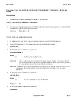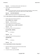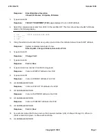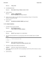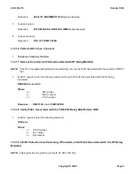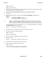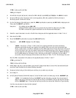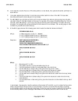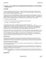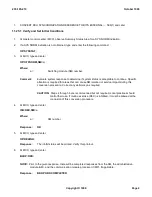
If
YES
, continue with next Step.
If
NO
, go to Step 20.
8.
At ALD2 circuit pack rear panel, connect the TMS directly to pins
20(T)
and
50 (R)
on the
940A
connector.
9.
Verify the TMS is set for the proper trunk circuit impedance, 600-ohm position for 600-ohm trunks or
900-ohm position for 900-ohm trunks.
10.
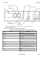
On the front panel of the ALD2 pack, press the
MENU
pushbutton repeatedly until
SET LEV
is displayed and
then press the
SELECT
pushbutton.
Response:
The display will read
ADJ LEV
.
A steady 1000-Hz reference tone is generated by the ALD2 for detection by the TMS.
The TMS indicated the output transmission level of the selected ALD2 pack.
11.
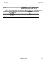
Read the output transmission level on the TMS and compare with the applicable value in Table 11.23-2 .
12.
Disconnect the TMS.
13.
Press the
SELECT
pushbutton to escape the
ADJ LEV
function.
Response:
LOC MODE
displayed on LED display.
14.
NOTE:
The values in Table 11.23-2 will result in meeting the Bellcore Technical Advisory
standard transmission level to the network of -24 dBm for SITs and -22 VU for announcements.
These values assume a 6 dB loss between the
T
and
R
outputs of the 14A and the input of the trunk
circuit. If the loss is less, then the values must be decreased accordingly. If the 14A is connected to
a 2-wire telephone line instead of a trunk circuit, as in a remote switching module (RSM) application,
the
T
and
R
outputs are connected to the 2-wire line via the AWH1 circuit pack. For this type of
connection, the preferred output transmission level shown in Table 11.23-2 should always be used.
Was the TMS measurement the same as the applicable value in Table 11.23-2 ?
If
YES
, go to Step 18.
If
NO
, continue with next Step.
15.
Notify office supervision and installation group that the output transmission level of the selected ALD2 pack
does NOT meet the Bellcore Technical Advisory standard.
16.
Postpone further testing of this ALD2 pack until the error condition is corrected.
17.
Go to Step 33.
18.
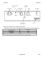
At front panel of selected ALD2 circuit pack, connect handset, with a modular plug, into the
HANDSET
jack.
19.
NOTE:
For installations that have the
START
input permanently grounded, the announcement
plays continuously; therefore, the announcement can be monitored by simply inserting the handset
into the
HANDSET
jack. The announcement cycle will be in process and should be of good quality.
Can the announcement be heard in the handset?
If
YES
, continue with next Step.
235-105-210
October 1999
Copyright © 1999
Page 2
Summary of Contents for 5ESS-2000
Page 96: ...235 105 210 October 1999 Copyright 1999 Page 2 ...
Page 184: ...235 105 210 October 1999 Copyright 1999 Page 3 ...
Page 300: ...13 STOP YOU HAVE COMPLETED THIS PROCEDURE 235 105 210 October 1999 Copyright 1999 Page 55 ...
Page 339: ...7 STOP YOU HAVE COMPLETED THIS PROCEDURE 235 105 210 October 1999 Copyright 1999 Page 13 ...
Page 342: ...235 105 210 October 1999 Copyright 1999 Page 2 ...
Page 359: ...235 105 210 October 1999 Copyright 1999 Page 5 ...
Page 609: ...2 STOP YOU HAVE COMPLETED THIS PROCEDURE 235 105 210 October 1999 Copyright 1999 Page 12 ...
Page 676: ...235 105 210 October 1999 Copyright 1999 Page 9 ...
Page 792: ...3 STOP YOU HAVE COMPLETED THIS PROCEDURE 235 105 210 October 1999 Copyright 1999 Page 9 ...
Page 799: ...Figure 11 36 3 1 Cleaning Points 235 105 210 October 1999 Copyright 1999 Page 7 ...
Page 801: ...235 105 210 October 1999 Copyright 1999 Page 9 ...
Page 839: ...2 STOP YOU HAVE COMPLETED THIS PROCEDURE 235 105 210 October 1999 Copyright 1999 Page 16 ...
Page 999: ...2 STOP YOU HAVE COMPLETED THIS PROCEDURE 235 105 210 October 1999 Copyright 1999 Page 13 ...
Page 1008: ...Figure 11 55 1 CTSNS DIP Switch Settings 235 105 210 October 1999 Copyright 1999 Page 2 ...
Page 1011: ...235 105 210 October 1999 Copyright 1999 Page 5 ...
Page 1053: ...235 105 210 October 1999 Copyright 1999 Page 15 ...
Page 1289: ...Figure 15 17 2 AMATPS Data Link 235 105 210 October 1999 Copyright 1999 Page 2 ...
Page 1292: ...235 105 210 October 1999 Copyright 1999 Page 5 ...
Page 1303: ...9 STOP YOU HAVE COMPLETED THIS PROCEDURE 235 105 210 October 1999 Copyright 1999 Page 2 ...
Page 1360: ...Figure 15 47 2 Typical SCANS III Link Diagram 235 105 210 October 1999 Copyright 1999 Page 2 ...
Page 1372: ...235 105 210 October 1999 Copyright 1999 Page 2 ...
Page 1374: ...235 105 210 October 1999 Copyright 1999 Page 4 ...
Page 1421: ...Table 1 1 O M Checklist 235 105 210 October 1999 Copyright 1999 Page 3 ...

