12. ROUTINE EXERCISE DESCRIPTION
12.1 GENERAL
This section provides a description of the
5ESS
®
-2000 switch routine exercise (REX) for the high capacity offices
capability. Included are detailed descriptions and examples of the REX craft interface and a set of guidelines for
establishing a schedule of tests for the Administration Module (AM), Communication Module (CM), and Switching
Modules/Switching Module-2000s (SMs/SM-2000s).
Section 13 contains detailed level procedures for the 5ESS-2000 switch REX for the high capacity offices
capability. Included are procedures for the AM, CM, and SMs/SM-2000s.
NOTE:
The Operational Support System (OSS) REX scheduler is a PC supported tool, and needs to be ordered.
This tool is strongly recommended for scheduling REX, as improper implementation of REX can overtax
system resources.
A new feature called ``automatic REX scheduler'' was introduced with the 5E8 software release. This feature is not
to be confused with ``REX automatic scheduling'' discussed in Section 12.5 of this document. With the new
``automatic REX scheduler'', the schedule is calculated and entered into RC/V views, and REX runs, all from one
command. With the old ``REX automatic scheduling'' the schedule must be calculated by the user and entered
manually, after which REX will run ``automatically'' every day. The new ``automatic REX scheduler'' performs the
same logical function as the ``OSS REX scheduler program'' (Section 12.10 ), but the new program resides in the
switch instead of a personal computer.
12.2 PURPOSE OF REX
The purpose of the 5ESS-2000 switch REX is to routinely schedule tests, in the AM, CM or SMs/SM-2000s, in order
to detect latent faults present in in-service units. Simply stated, REX is nothing more than an automatic scheduler of
tests. The types of tests that REX schedules are dependent upon the module type, either AM, CM, or SM/SM-2000.
In the AM, the REX processor searches the Unit Control Block (UCB) records of the Equipment Configuration Data
base (ECD) for hardware communities that can be removed from service. REX can only be performed on equipment
that has duplex mode configuration, not simplex mode. When REX locates a hardware community that can be
removed from service, REX requests a remove diagnosis and restore of the hardware community. When the
exercise of the hardware community is completed, REX resumes searching the data base for the next hardware
community that can be removed from service and exercised.
It should be noted that in the AM, REX is allowed to be performed only on the control unit (CU). REX is prohibited on
the following devices:
IOP (input/output processor)
DFC (disk file controller)
MHD (moving head disk)
CNI (common network interface), a stored program control system.
In the CM, two test types are available for scheduling. They are a full and partial diagnostic, described as follows:
Full diagnostic (DGN):
A full diagnostic results in a conditional restore request including the Trouble Location
Procedure (TLP) option. A conditional restore consists of: a remove of the target unit if it is not already
out-of-service, a full diagnostic on the unit, and a restore of the unit to service if the diagnostic result was all
tests pass (ATP) or conditional all tests pass (CATP).
235-105-210
October 1999
Copyright © 1999
Page 1
Summary of Contents for 5ESS-2000
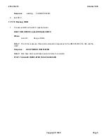
Page 96: ...235 105 210 October 1999 Copyright 1999 Page 2 ...
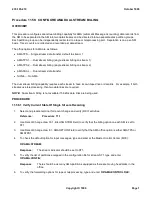
Page 184: ...235 105 210 October 1999 Copyright 1999 Page 3 ...
Page 300: ...13 STOP YOU HAVE COMPLETED THIS PROCEDURE 235 105 210 October 1999 Copyright 1999 Page 55 ...
Page 339: ...7 STOP YOU HAVE COMPLETED THIS PROCEDURE 235 105 210 October 1999 Copyright 1999 Page 13 ...
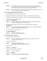
Page 342: ...235 105 210 October 1999 Copyright 1999 Page 2 ...
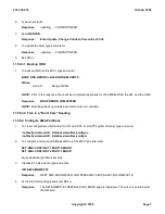
Page 359: ...235 105 210 October 1999 Copyright 1999 Page 5 ...
Page 609: ...2 STOP YOU HAVE COMPLETED THIS PROCEDURE 235 105 210 October 1999 Copyright 1999 Page 12 ...
Page 676: ...235 105 210 October 1999 Copyright 1999 Page 9 ...
Page 792: ...3 STOP YOU HAVE COMPLETED THIS PROCEDURE 235 105 210 October 1999 Copyright 1999 Page 9 ...
Page 799: ...Figure 11 36 3 1 Cleaning Points 235 105 210 October 1999 Copyright 1999 Page 7 ...
Page 801: ...235 105 210 October 1999 Copyright 1999 Page 9 ...
Page 839: ...2 STOP YOU HAVE COMPLETED THIS PROCEDURE 235 105 210 October 1999 Copyright 1999 Page 16 ...
Page 999: ...2 STOP YOU HAVE COMPLETED THIS PROCEDURE 235 105 210 October 1999 Copyright 1999 Page 13 ...
Page 1008: ...Figure 11 55 1 CTSNS DIP Switch Settings 235 105 210 October 1999 Copyright 1999 Page 2 ...
Page 1011: ...235 105 210 October 1999 Copyright 1999 Page 5 ...
Page 1053: ...235 105 210 October 1999 Copyright 1999 Page 15 ...
Page 1289: ...Figure 15 17 2 AMATPS Data Link 235 105 210 October 1999 Copyright 1999 Page 2 ...
Page 1292: ...235 105 210 October 1999 Copyright 1999 Page 5 ...
Page 1303: ...9 STOP YOU HAVE COMPLETED THIS PROCEDURE 235 105 210 October 1999 Copyright 1999 Page 2 ...
Page 1360: ...Figure 15 47 2 Typical SCANS III Link Diagram 235 105 210 October 1999 Copyright 1999 Page 2 ...
Page 1372: ...235 105 210 October 1999 Copyright 1999 Page 2 ...
Page 1374: ...235 105 210 October 1999 Copyright 1999 Page 4 ...
Page 1421: ...Table 1 1 O M Checklist 235 105 210 October 1999 Copyright 1999 Page 3 ...

