


DUMP:DAYLOG
command to retrieve the REX data from the daylog file and the
CHG:LPS
command to have
logging turn on.
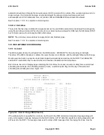
Each page can be accessed by selecting view 8.3 on the RC/V menu (Page 196). A series of prompts will ask you if
you wish to update the existing page, review it, etc.
For the three test types (DGN, FAB, and ELS), there is a position associated with each day the test is to run. FAB
and ELS tests do not apply to CM, and any attempt to alter the CM page for these tests will result in an error. An ``F''
in a position indicates run a full test on the day corresponding to that position. An ``N'' indicates no tests are to be
run. In the case of the CM, a ``P'' (for partial test) in the DGN column will schedule the CM switch test. Partial test
only applies to the CM and not the SMs/SM-2000s.
12.5.2 Digital Network Unit - SONET (DNU-S)
In the 5E10 and later software releases, the FI SWITCH INT field on Recent Change View 8.1 allows the DNU-S
SFI switching by REX. The default value for FI SWITCH INT is 28 days. SFI switching causes a glitch which
generates transient errors on the facilities. The FI SWITCH INT allows the user to set how often the SFIs will switch
due to REX. REX switches the SFIs ACT/STBY every FI SWITCH INT days. The DNU-S SFI switching can be
disabled by setting the FI SWITCHINT field to a 0. The current status of the DNU-S is available on MCC page 1510.
12.6 REX MCC PAGES
12.6.1 GENERAL
A set of REX master control center (MCC) pages are provided to help manage REX activities in large offices. These
pages will allow the operating company personnel to monitor REX at either a high level view or at a module-level
view. The new pages are the REX SUMMARY pages, the SM REX STATUS page, and the CM REX STATUS page.
12.6.2 REX SUMMARY PAGE
There are four pages which comprise the REX summary pages (1271 - SM 1 - 48 REX STATUS, 1272 - SM 49 - 96
REX STATUS, 1273 - SM 97 - 144 REX STATUS, and 1274 - SM 145 - 192 REX STATUS). These pages are used
to display the REX status of 48 SMs/SM-2000s at a glance.
The information displayed for each operational SM/SM-2000 will be the SM/SM-2000 number and any test type that
is in-progress or inhibited. The test displayed for in-progress is ``IP'' and that for inhibit is ``INH''. The in-progress
status has a higher procedure than the FAB test type is inhibited for test, and in-progress status will be displayed for
DGN test and the inhibited status for FAB will not show up. If REX is allowed and not in-progress for any test type,
no state text will be displayed. Only the SM/SM-2000 number will appear.
If the DGN test type appears as inhibited, either the module has been inhibited for DGN test or a unit in the module
has been inhibited for DGN test. To determine which one is inhibited, use the
OP:REXINH
command or display the
appropriate SM status page.
The video attributes for the in-progress status are black on yellow for color terminals and reverse video for black and
white terminals. The video attributes for the inhibit status are blue on yellow for color terminals and reverse video for
black and white. All other states will be normal video (white on black).
There is also an indicator on MCC Page 1271 to display summary status for the CM in the same manner as for the
SMs/SM-2000s. For the CM, only the DGN test type will show up as being inhibited or in-progress. Like the
SMs/SM-2000s, if you need to determine whether the CM module has been inhibited for DGN test or a unit has
been inhibited, use the
OP:REXINH
command or display the CM status page.
There are menu commands to direct the craft to the correct detail page for the other REX SUMMARY pages, to the
SM REX STATUS page for a particular SM/SM-2000, and to the CM REX STATUS page. A copy of the REX
235-105-210
October 1999
Copyright © 1999
Page 7
Summary of Contents for 5ESS-2000
Page 96: ...235 105 210 October 1999 Copyright 1999 Page 2 ...
Page 184: ...235 105 210 October 1999 Copyright 1999 Page 3 ...
Page 300: ...13 STOP YOU HAVE COMPLETED THIS PROCEDURE 235 105 210 October 1999 Copyright 1999 Page 55 ...
Page 339: ...7 STOP YOU HAVE COMPLETED THIS PROCEDURE 235 105 210 October 1999 Copyright 1999 Page 13 ...
Page 342: ...235 105 210 October 1999 Copyright 1999 Page 2 ...
Page 359: ...235 105 210 October 1999 Copyright 1999 Page 5 ...
Page 609: ...2 STOP YOU HAVE COMPLETED THIS PROCEDURE 235 105 210 October 1999 Copyright 1999 Page 12 ...
Page 676: ...235 105 210 October 1999 Copyright 1999 Page 9 ...
Page 792: ...3 STOP YOU HAVE COMPLETED THIS PROCEDURE 235 105 210 October 1999 Copyright 1999 Page 9 ...
Page 799: ...Figure 11 36 3 1 Cleaning Points 235 105 210 October 1999 Copyright 1999 Page 7 ...
Page 801: ...235 105 210 October 1999 Copyright 1999 Page 9 ...
Page 839: ...2 STOP YOU HAVE COMPLETED THIS PROCEDURE 235 105 210 October 1999 Copyright 1999 Page 16 ...
Page 999: ...2 STOP YOU HAVE COMPLETED THIS PROCEDURE 235 105 210 October 1999 Copyright 1999 Page 13 ...
Page 1008: ...Figure 11 55 1 CTSNS DIP Switch Settings 235 105 210 October 1999 Copyright 1999 Page 2 ...
Page 1011: ...235 105 210 October 1999 Copyright 1999 Page 5 ...
Page 1053: ...235 105 210 October 1999 Copyright 1999 Page 15 ...
Page 1289: ...Figure 15 17 2 AMATPS Data Link 235 105 210 October 1999 Copyright 1999 Page 2 ...
Page 1292: ...235 105 210 October 1999 Copyright 1999 Page 5 ...
Page 1303: ...9 STOP YOU HAVE COMPLETED THIS PROCEDURE 235 105 210 October 1999 Copyright 1999 Page 2 ...
Page 1360: ...Figure 15 47 2 Typical SCANS III Link Diagram 235 105 210 October 1999 Copyright 1999 Page 2 ...
Page 1372: ...235 105 210 October 1999 Copyright 1999 Page 2 ...
Page 1374: ...235 105 210 October 1999 Copyright 1999 Page 4 ...
Page 1421: ...Table 1 1 O M Checklist 235 105 210 October 1999 Copyright 1999 Page 3 ...