


Procedure 4.25: LOAD TAPE INTO DAT TAPE DRIVE
PROCEDURE
1.
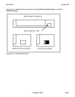
Verify that the tape cartridges write-protect switch is set correctly.
For write-protection the light-colored tab should NOT be visible. For write- enable, the tab should be visible.
2.
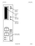
Check the LEDs on the tape drive front panel to make sure the drive is not currently functioning.
Both the green and amber LEDs should not be illuminated. It is not recommended to interrupt the tape drive
if the green LED is blinking. A steady green LED indicates a data cartridge is in the drive and the drive is
ready for activity. There is a problem if the amber LED is blinking.
3.
Insert the tape cartridge so the manufacturer's label is facing up and the write-enable switch on the cartridge
is facing toward you.
4.
Gently push the tape cartridge into the tape drive until the end with the write-enable switch is flush with the
tape drive front panel. The tape drive is auto-loading and will pull the tape cartridge the remainder of the way
into the drive.
DO NOT
force the cartridge into the drive. The green LED will blink for a few seconds while
the tape is loading then remain steady once the loading process is complete.
5.
STOP. YOU HAVE COMPLETED THIS PROCEDURE.
235-105-210
October 1999
Copyright © 1999
Page 1
Summary of Contents for 5ESS-2000
Page 96: ...235 105 210 October 1999 Copyright 1999 Page 2 ...
Page 184: ...235 105 210 October 1999 Copyright 1999 Page 3 ...
Page 300: ...13 STOP YOU HAVE COMPLETED THIS PROCEDURE 235 105 210 October 1999 Copyright 1999 Page 55 ...
Page 339: ...7 STOP YOU HAVE COMPLETED THIS PROCEDURE 235 105 210 October 1999 Copyright 1999 Page 13 ...
Page 342: ...235 105 210 October 1999 Copyright 1999 Page 2 ...
Page 359: ...235 105 210 October 1999 Copyright 1999 Page 5 ...
Page 609: ...2 STOP YOU HAVE COMPLETED THIS PROCEDURE 235 105 210 October 1999 Copyright 1999 Page 12 ...
Page 676: ...235 105 210 October 1999 Copyright 1999 Page 9 ...
Page 792: ...3 STOP YOU HAVE COMPLETED THIS PROCEDURE 235 105 210 October 1999 Copyright 1999 Page 9 ...
Page 799: ...Figure 11 36 3 1 Cleaning Points 235 105 210 October 1999 Copyright 1999 Page 7 ...
Page 801: ...235 105 210 October 1999 Copyright 1999 Page 9 ...
Page 839: ...2 STOP YOU HAVE COMPLETED THIS PROCEDURE 235 105 210 October 1999 Copyright 1999 Page 16 ...
Page 999: ...2 STOP YOU HAVE COMPLETED THIS PROCEDURE 235 105 210 October 1999 Copyright 1999 Page 13 ...
Page 1008: ...Figure 11 55 1 CTSNS DIP Switch Settings 235 105 210 October 1999 Copyright 1999 Page 2 ...
Page 1011: ...235 105 210 October 1999 Copyright 1999 Page 5 ...
Page 1053: ...235 105 210 October 1999 Copyright 1999 Page 15 ...
Page 1289: ...Figure 15 17 2 AMATPS Data Link 235 105 210 October 1999 Copyright 1999 Page 2 ...
Page 1292: ...235 105 210 October 1999 Copyright 1999 Page 5 ...
Page 1303: ...9 STOP YOU HAVE COMPLETED THIS PROCEDURE 235 105 210 October 1999 Copyright 1999 Page 2 ...
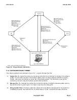
Page 1360: ...Figure 15 47 2 Typical SCANS III Link Diagram 235 105 210 October 1999 Copyright 1999 Page 2 ...
Page 1372: ...235 105 210 October 1999 Copyright 1999 Page 2 ...
Page 1374: ...235 105 210 October 1999 Copyright 1999 Page 4 ...
Page 1421: ...Table 1 1 O M Checklist 235 105 210 October 1999 Copyright 1999 Page 3 ...