


If
YES
, go to Step 12.
If
NO
, continue with next Step.
9.
Notify office supervision and installation group that selected ALD1 circuit pack output transmission level does
NOT meet the Bellcore Technical Advisory standard.
10.
Postpone further testing of this ALD1 pack until the error condition is corrected.
11.
Go to Step 19.
12.
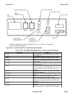
On the front panel of the ALD1 circuit pack, depress the
SET LEVEL/NORMAL
pushbutton switch to
NORMAL
.
Response:
The
SET LEVEL/NORMAL
LED goes off.
Selected ALD1 circuit pack is restored to service.
13.
NOTE:
For installations that have the
START
input permanently grounded, the announcement
cycles continuously. If the
START
input is not permanently grounded, insertion of the handset will
start the announcement cycle at the beginning. The announcement should be of good audio quality.
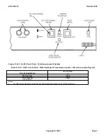
At front panel of selected ALD1 circuit pack (Figure 11.22-1 ), connect handset (G3CR-type or equivalent) in
the
AUDIO MONITOR
jack on the circuit pack.
Response:
Announcement can be heard in the handset.
14.
Use the handset to monitor at least one full cycle of the recorded announcement.
15.
Is recorded announcement of satisfactory quality?
If
YES
, go to Step 17.
If
NO
, continue with next Step.
16.
Report error condition to installation group and office supervision.
17.
Disconnect handset.
Response:
Selected ALD1 circuit pack is returned to service.
18.
Notify office supervision that selected ALD1 pack is in service.
19.
Does another ALD1 circuit pack remain to be tested?
If
YES
, go to Step 1.
If
NO
,
STOP. YOU HAVE COMPLETED THIS PROCEDURE.
235-105-210
October 1999
Copyright © 1999
Page 2
Summary of Contents for 5ESS-2000
Page 96: ...235 105 210 October 1999 Copyright 1999 Page 2 ...
Page 184: ...235 105 210 October 1999 Copyright 1999 Page 3 ...
Page 300: ...13 STOP YOU HAVE COMPLETED THIS PROCEDURE 235 105 210 October 1999 Copyright 1999 Page 55 ...
Page 339: ...7 STOP YOU HAVE COMPLETED THIS PROCEDURE 235 105 210 October 1999 Copyright 1999 Page 13 ...
Page 342: ...235 105 210 October 1999 Copyright 1999 Page 2 ...
Page 359: ...235 105 210 October 1999 Copyright 1999 Page 5 ...
Page 609: ...2 STOP YOU HAVE COMPLETED THIS PROCEDURE 235 105 210 October 1999 Copyright 1999 Page 12 ...
Page 676: ...235 105 210 October 1999 Copyright 1999 Page 9 ...
Page 792: ...3 STOP YOU HAVE COMPLETED THIS PROCEDURE 235 105 210 October 1999 Copyright 1999 Page 9 ...
Page 799: ...Figure 11 36 3 1 Cleaning Points 235 105 210 October 1999 Copyright 1999 Page 7 ...
Page 801: ...235 105 210 October 1999 Copyright 1999 Page 9 ...
Page 839: ...2 STOP YOU HAVE COMPLETED THIS PROCEDURE 235 105 210 October 1999 Copyright 1999 Page 16 ...
Page 999: ...2 STOP YOU HAVE COMPLETED THIS PROCEDURE 235 105 210 October 1999 Copyright 1999 Page 13 ...
Page 1008: ...Figure 11 55 1 CTSNS DIP Switch Settings 235 105 210 October 1999 Copyright 1999 Page 2 ...
Page 1011: ...235 105 210 October 1999 Copyright 1999 Page 5 ...
Page 1053: ...235 105 210 October 1999 Copyright 1999 Page 15 ...
Page 1289: ...Figure 15 17 2 AMATPS Data Link 235 105 210 October 1999 Copyright 1999 Page 2 ...
Page 1292: ...235 105 210 October 1999 Copyright 1999 Page 5 ...
Page 1303: ...9 STOP YOU HAVE COMPLETED THIS PROCEDURE 235 105 210 October 1999 Copyright 1999 Page 2 ...
Page 1360: ...Figure 15 47 2 Typical SCANS III Link Diagram 235 105 210 October 1999 Copyright 1999 Page 2 ...
Page 1372: ...235 105 210 October 1999 Copyright 1999 Page 2 ...
Page 1374: ...235 105 210 October 1999 Copyright 1999 Page 4 ...
Page 1421: ...Table 1 1 O M Checklist 235 105 210 October 1999 Copyright 1999 Page 3 ...