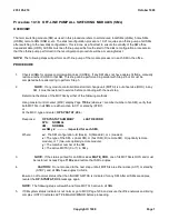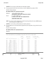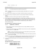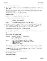
vvv
=
1000, 600, 322, 340
Note 3
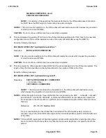
wwyy
=
[S, M, L)][ 0, 25, 50, 75, or 100% AMA]
Note 4
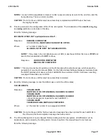
zzzz
=
1000, 600, 322, 340, or Unknown
Note 5
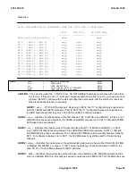
CAUTION:
The columns under the ``VTOCS'' and ``SG DATA BASE'' headings must agree with each other
line for line. If they do not or if ``Unknown'' appears anywhere in either column, you have a serious
problem. Do NOT continue with the disk reconfiguration procedure until the problem is resolved.
Seek technical assistance if necessary.
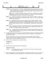
NOTE 1:
xxxx
VTOCS of the disk pair. Beginning in 5E12, the "11" configuration is supported on
both the 3B20D and 3B21D processor. Prior to 5E12 the "11" configuration was only supported on
the 3B21D processor and then only in 5E10 and 5E11 software release.
NOTE 2:
uuu
Identifies the physical size of the first disk pair (RT 0 or MHD 0 and MHD 1). In 5E12, only 1
GB SCSI disk drives are allowed on the 3B20D and 3B21D processors. In 5E11, 1 GB and 600 MB
SCSI disk drives are allowed.
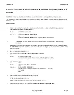
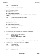
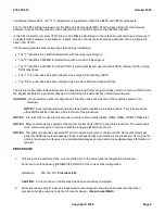
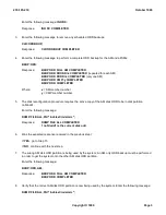
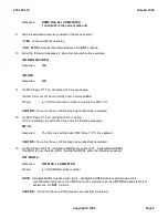
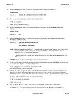
NOTE 3:
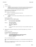
vvv
Identifies the physical size of the second disk pair (RT 1 or MHD 2 and MHD 3). In 5E12,
only 1 GB SCSI disk drives are allowed on the 3B20D and 3B21D processors. In 5E11, 1 GB and
600 MB SCSI disk drives are allowed. The 1 GB and 600 MB are valid secondary disk pair sizes for
5E11. For software releases prior to 5E11, the 322 MB drives may still be used for the secondary
disk pair.
NOTE 4:
wwyy
Identifies the logical size of the optional disk pairs (ww) as being either Small (S) 322 MB,
or Medium (M) 600 MB, or Large (L) 1 GB. The percentage (yy) of space allocated to AMA on the
disk; 50, 75 or 100% AMA is allowed for 5E10 and later.
NOTE 5:
zzzz
Identifies the physical size of the disk pair. If one MHD is a 322 MB SCSI (Small) and the
other is a 600 MB SCSI then the disk pair will be considered a 322 MB SCSI. The 340 MB drives are
not supported for 5E10 and later.
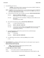
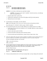
27.
The following steps (28 through 37) utilize a conversational dialogue to determine the parameters for this disk
reconfiguration procedure. They must be performed from an RCV or STLWS terminal. They
cannot
be
performed from the MCC.
Some of the steps in this procedure are conditional and may not be executed during a specific disk
reconfiguration procedure. Error messages (not shown in the following steps) could also be displayed. If this
happens, follow the instructions displayed on the terminal.
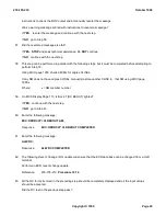
28.
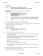
Enter the following message at an RCV or STLWS terminal.
RCV:MENU:SH
Response:
#
29.
Enter the following message at the RCV or STLWS terminal.
/updtmp/site/checkvars
Response:
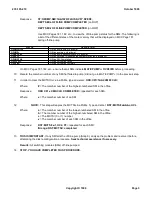
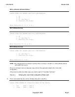
Screen Display responses in Steps 30 through 35 may or may not be displayed. Step 36
Screen Display will be displayed.
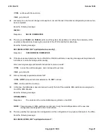
30.
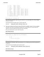
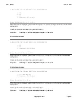
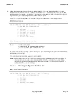
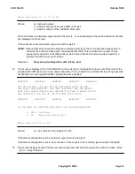
This screen determines the current disk configuration and is displayed only if there is an error in the interface
between the
diskcon
script and the
checkvars
script. The screens are different for the software release.
235-105-210
October 1999
Copyright © 1999
Page 8
Summary of Contents for 5ESS-2000
Page 96: ...235 105 210 October 1999 Copyright 1999 Page 2 ...
Page 184: ...235 105 210 October 1999 Copyright 1999 Page 3 ...
Page 300: ...13 STOP YOU HAVE COMPLETED THIS PROCEDURE 235 105 210 October 1999 Copyright 1999 Page 55 ...
Page 339: ...7 STOP YOU HAVE COMPLETED THIS PROCEDURE 235 105 210 October 1999 Copyright 1999 Page 13 ...
Page 342: ...235 105 210 October 1999 Copyright 1999 Page 2 ...
Page 359: ...235 105 210 October 1999 Copyright 1999 Page 5 ...
Page 609: ...2 STOP YOU HAVE COMPLETED THIS PROCEDURE 235 105 210 October 1999 Copyright 1999 Page 12 ...
Page 676: ...235 105 210 October 1999 Copyright 1999 Page 9 ...
Page 792: ...3 STOP YOU HAVE COMPLETED THIS PROCEDURE 235 105 210 October 1999 Copyright 1999 Page 9 ...
Page 799: ...Figure 11 36 3 1 Cleaning Points 235 105 210 October 1999 Copyright 1999 Page 7 ...
Page 801: ...235 105 210 October 1999 Copyright 1999 Page 9 ...
Page 839: ...2 STOP YOU HAVE COMPLETED THIS PROCEDURE 235 105 210 October 1999 Copyright 1999 Page 16 ...
Page 999: ...2 STOP YOU HAVE COMPLETED THIS PROCEDURE 235 105 210 October 1999 Copyright 1999 Page 13 ...
Page 1008: ...Figure 11 55 1 CTSNS DIP Switch Settings 235 105 210 October 1999 Copyright 1999 Page 2 ...
Page 1011: ...235 105 210 October 1999 Copyright 1999 Page 5 ...
Page 1053: ...235 105 210 October 1999 Copyright 1999 Page 15 ...
Page 1289: ...Figure 15 17 2 AMATPS Data Link 235 105 210 October 1999 Copyright 1999 Page 2 ...
Page 1292: ...235 105 210 October 1999 Copyright 1999 Page 5 ...
Page 1303: ...9 STOP YOU HAVE COMPLETED THIS PROCEDURE 235 105 210 October 1999 Copyright 1999 Page 2 ...
Page 1360: ...Figure 15 47 2 Typical SCANS III Link Diagram 235 105 210 October 1999 Copyright 1999 Page 2 ...
Page 1372: ...235 105 210 October 1999 Copyright 1999 Page 2 ...
Page 1374: ...235 105 210 October 1999 Copyright 1999 Page 4 ...
Page 1421: ...Table 1 1 O M Checklist 235 105 210 October 1999 Copyright 1999 Page 3 ...

